
13.2 Low Power BLE Application Design
When designing a wireless Bluetooth® Application, the advertisement and connection intervals managed by the BLE stack play a key role in determining when the device enters and exits sleep modes. The BLE stack supports two types of Low-power or Sleep modes:
Sleep
Deep Sleep
Sleep and Deep Sleep modes are equivalent to Standby and Backup modes, and these terms may be used interchangeably throughout this online reference guide.
The following table lists the various functionality/modules of the device that are available in the Low-power modes supported by the BLE stack.
|
Function |
Sleep |
Deep Sleep |
|---|---|---|
Legacy ADV | Available | Available |
Extended ADV (Coded PHY) | Available | Not supported |
BLE Connection | Available | The device can begin advertising while in the Deep Sleep Low-power mode and, after establishing a BLE connection, transition to the Sleep low power mode. |
Peripherals | Available(1) | Limited wake-up sources are available |
Device wakes up from reset after exiting the Sleep mode | No | Yes |
System RAM | Available | Not retained |
Backup RAM | Not used by application or BLE stack | Available and used by application and BLE stack |
Timer used to manage sleep and wake-up times | Wireless Subsystem manages time intervals based on ADV/Connection intervals setup by API calls to BLE Stack library | RTC |
ADV intervals recommended | No min/max ADV interval | Min ADV interval = 500 ms for power consumption savings |
|
Note: For more details, refer to the
PIC32CX-BZ3/PIC32CX-BZ36 SoC and WBZ35x Module
Family Data Sheet (DS70005541) in the
Reference Documentation from Related
Links.
| ||
Sleep/ Standby Low Power Mode
Application Sleep Duration Control
The BLE stack enables the system to enter Low Power mode when there is no ongoing data transmission or reception, or during the BLE advertisement or connection intervals. The system sleep is managed automatically by the stack and cannot be directly controlled through a parameter or API call.
Device Operation in Sleep Low Power Mode
While the system is in the Sleep mode, it disables the system PLL clock and the stops system tick. The user must adjust the FreeRTOS timer to account for the duration spent in Low Power mode. The RTC timer can continue running during low power modes and corrects the FreeRTOS timer offset. Factors such as BLE activity intervals, external interrupts (for example, GPIO), or peripheral interrupts determine the total time the system spends in Sleep mode. Peripherals permitted to operate in Standby or Sleep Low Power mode can continue functioning during the Sleep mode. In Deep Sleep or Backup mode, only specific peripherals, such as the RTC and INT0, can remain active.
Enabling Sleep/Standby Low Power Mode
| Application Example | Description | Reference |
|---|---|---|
| BLE Sleep Mode Legacy Advertisements | Implements Sleep Low Power mode with periodic BLE legacy advertisements. | See BLE Legacy Advertisements from Related Links. |
| BLE Extended Advertisements | Implements Sleep Low Power with periodic BLE extended (coded PHY) advertisements. | See BLE Extended Advertisements from Related Links. |
| BLE Sensor | Implements sleep low power mode in a BLE connection oriented application and data exchange using Microchip transparent UART service. This application also has peripherals that are enabled to run in Standby/Sleep Low Power mode. | See BLE Sensor with Touch from Related Links. |
| BLE Custom Service | Implements Sleep Low Power in a BLE connection oriented application and data exchange using custom service. This application does not have peripherals continuing to run in Standby/Sleep Low Power mode | See BLE Custom Service from Related Links. |
Generating Sleep Mode Code with MPLAB Code Configurator
- The user
must enable the system Sleep Mode in BLE stack H3
component configuration. After enabling this, the
system requests to enable dependent components like
RTC (timer source during sleep).
Figure 13-1. Enable Sleep Mode 
- Upon
enabling Sleep mode, the system automatically sets
the FreeRTOS related settings.
- In the “RTOS Configuration” drop-down menu,
perfrom the following steps:
- Set the “Tick Mode” to Tickless_Idle. This allows the system to suppress periodic tick interrupts when idle, reducing power consumption.
- Set the “Expected idle time before sleep” to 5 (ms).
Figure 13-2. FreeRTOS Settings 
- Enabling Tick Hook.
- Find the option labeled “Tick Hook.”
- Check the Use Tick Hook. This allows the user to add custom code that executes during each tick interrupt.
Figure 13-3. Tick Hook 
- RTC peripheral library will be added and
configured.Note: RTC counter must not be reset (
RTC_Timer32CounterSet()) arbitrarily when the system is running.
- In the “RTOS Configuration” drop-down menu,
perfrom the following steps:
- The user
must manually set the RTC clock source, the
following are the four options:
- FRC (±1% offset)
- LPRC (with larger offset, < ±5%)
- POSC – Candidate of the clock source (better clock accuracy)
- SOSC – Candidate of the clock source (better clock accuracy)
Note: Select POSC/SOSC as the RTC clock source, as other clock sources can impact BLE connection stability.Figure 13-4. Clock Configuration 
- Manually
setting RTC clock source – POSC.
- Choose “POSC” in “Clock Configuration”.
- The user must configure as illustrated in the following figure.
Figure 13-5. Manually Setting RTC Clock Source – POSC 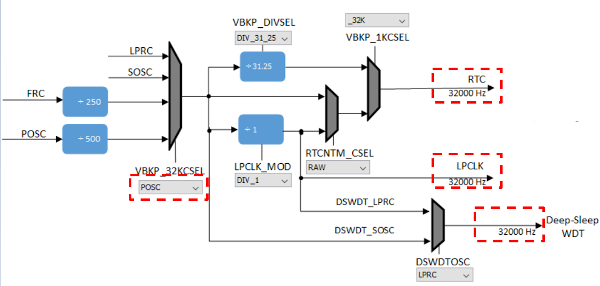
- Manually
Setting RTC clock source – SOSC, by turning on SOSC
and then choose SOSC as illustrated in the following
figure.
Figure 13-6. Manually Setting RTC Clock Source – SOSC 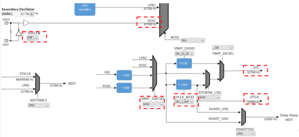 Note: The users can only select one clock source POSC or SOSC, steps mention how to choose either.
 -
It is recommended to use 48MHz as SYS_CLOCK for better power savings. This can be configured by setting SPLLPOSTDIV1 to
2as shown below.Figure 13-7. . 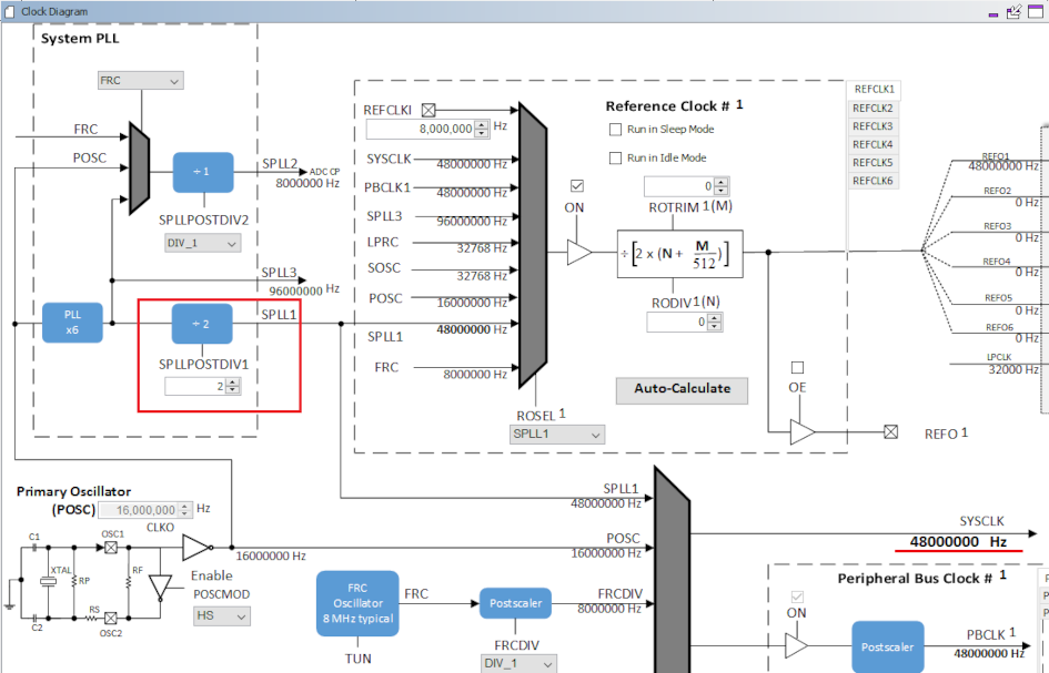
-
Ensure that JTAG Enable is disabled by clearing the JTAGEN bit in CFGCON0 (Configuration Control Register 0) as shown below. This code snippet can be added to SYS_Initialize().
CFG_REGS->CFG_CFGCON0CLR = CFG_CFGCON0_JTAGEN_Msk; - All
unused pins in the application needs to be set to
Input mode and the pull-down must be
enabled for these pins.
The user can configure this through pin configuration in Harmony3 Configurator. For more details, see the following figure.
Figure 13-8. Pin Settings 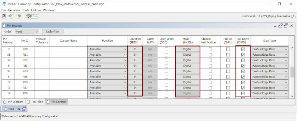
- For more details on code generation, refer to the MPLAB Code Configurator (MCC) Code Generation from Related Links.
Sleep-Related Code Implementation Locations
| Implementation | Location |
|---|---|
| BT Sleep Mode | BLE stack library |
| System Sleep Mode | device_sleep.c |
| Execute BT/System Sleep | app_idle_task.c |
| RTC Based Tickless Idle Mode | app_idle_task.c |
User Code for Sleep/Standby Low Power Mode Entry

- In order
for the system to enter Sleep mode, the system needs
to request Bluetooth® wireless
subsystem to sleep. This is accomplished by calling
the
BT_SYS_EnterSleepMode()API for BLE.Figure 13-9. BT_SYS_EnterSleepMode()API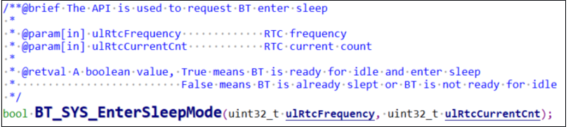
- The API
to call to ensure subsystem is sleeping (inactive)
or ready for system to enter Sleep mode is the
BT_SYS_AllowSystemSleepAPI.Figure 13-10. BT_SYS_AllowSystemSleepAPI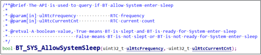
- If the
expected sleep time is greater than 5 ms, the system
is allowed to enter Sleep mode by checking for two
conditions:
- Bluetooth subsystem is inactive.
eTaskConfirmSleepModeStatus()returnseNoTasksWaitingTimeout. For more information, refer to the eTaskConfirmSleepModeStatus in Reference Documentation from Related Links.
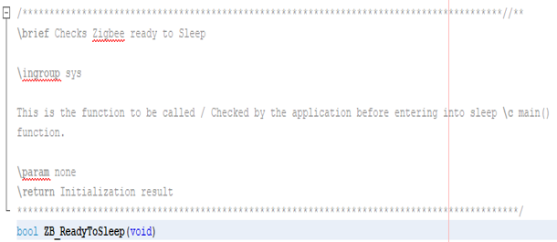
Note: The user can also add their own condition to be checked before system goes to sleep, for example, do not enter system sleep if data transmission over UART is active.Pseudo code in RTC based Tickless Idle Mode: ``` if ((BT_SYS_AllowSystemSleep() || ZB_ReadyToSleep()) && ( eTaskConfirmSleepModeStatus() != eAbortSleep ) && (user_condition)) { //Enter System Sleep Mode DEVICE_EnterSleepMode (); //RTC Based Tickless Idle Mode } ``` - When both
the conditions as mentioned in point 3 are met,
enter RTC based Tickless Idle mode (stops the system
tick, uses the RTC timer to set the sleep time,
disables interrupts).
- The system enters Sleep mode after setting the
RTC based Tickless Idle mode by calling
Device_EnterSleepMode()API and then the system executes the Wait for Interrupt (WFI) instruction.Figure 13-11. RTC Based Tickless Idle Mode Entry Sequence 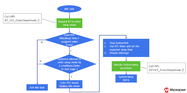
- The system enters Sleep mode after setting the
RTC based Tickless Idle mode by calling
Exiting Sleep Mode
- RTC timeout
- BLE event
- GPIO interrupt
- Calling
DEVICE_ExitSleepMode()API to begin the wake-up process. - After exiting the Sleep mode, interrupts must be re-enabled to allow execution of the interrupt service routines.
- Interrupts are initially disabled because the
system tick needs to be compensated (as required by
Tickless IDLE mode in FreeRTOS).
Figure 13-12. Exiting Sleep Mode Flow Chart 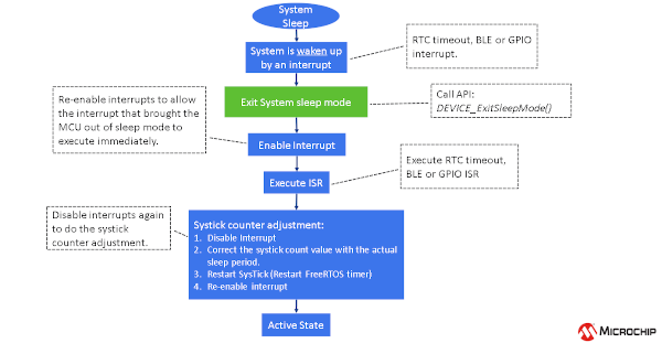
Deep Sleep/Backup Low Power Mode
Application Control of Sleep Duration
The user application controls how long the device remains in Deep Sleep Low Power mode. When the user sets the advertisement interval and enables Deep Sleep mode in the BLE_Stack component within the MCC, the system automaticalluy generates all necessary APIs for entering and exiting Deep Sleep. The user application must enable deep sleep advertising and manage the sleep and wake-up durations according to the chosen advertisement interval.
Unlike Sleep mode, which relies on a timer within the wireless subsystem
to manage sleep and wake-up periods, the Deep Sleep mode does not
have access to this timer. Instead, the RTC timer available during
Deep Sleep wakes the device through its interrupt, configured
according to the Deep Sleep advertisement interval. The user can
transition the device into Deep Sleep Low Power mode after receiving
the BLE_GAP_EVT_ADV_COMPL event from the BLE
stack.
Device Operation in Deep Sleep Low Power Mode
When the application layer initiates the BLE stack to enable deep sleep advertising, the BLE stack backs up advertising parameters and application data into backup RAM and performs a one-time advertisement event.
The application layer then puts the system in Deep Sleep mode and controls deep sleep wake-up time using the RTC timer. The user is responsible for putting the system into Deep Sleep mode and controlling the wake-up using the RTC.
Based on the RTC Timer interval, the device wakes up from Deep Sleep Low Power mode. Exiting Deep Sleep mode is similar to Power-On Reset (POR). Backup RAM saves the adv parameters through a reset; upon wake-up, the BLE stack is able to continue advertising based on the data retained in backup RAM.
Device Start-Up and Initialization Timing
The start-up and initialization code for the device differs and optimizes
to enable fast completion of initialization after a reset caused by
waking up from Deep Sleep Low Power mode. The MCC generates the
DEVICE_DeepSleepIntervalCal API to
calibrate the sleep duration based on the advertising interval
chosen. The device’s start-up and initialization procedures optimize
to make the device enter Deep Sleep Low Power mode as soon as
possible. The device spends approximately 10 ms during start-up and
firmware initialization. The average start-up time for the device is
1.5 ms. The firmware initialization time for various applications
can change based on the user’s choice of peripherals and clocks to
initialize.
Maintaining I/O State after Reset in Deep Sleep Mode
DEVICE_ClearDeepSleepReg()
MPLAB Code Configurator Usage for Deep Sleep Mode
- In MPLAB® X IDE, open MCC and create a new Harmony project.
- Add
required components to the Project Graph.Note: The application being developed determines whether some components are optional.
Figure 13-14. Deep Sleep Mode Project Graph 
- Select
the BLE Stack in the Project Graph tab.
- Configure the following settings for “BLE stack”
component. The slower the advertising interval,
the less current consumption. User can select
their desired interval.
Figure 13-15. BLE Stack Configuration Options Settings 
- Configure the following settings for “BLE stack”
component. The slower the advertising interval,
the less current consumption. User can select
their desired interval.
- Select
“RTC” component in the Project Graph tab.
- Configure the following settings for “RTC”
component.
Figure 13-16. RTC Component Configuration Options Settings 
- Configure the following settings for “RTC”
component.
- Go to
MPLAB® Code
Configurator>Harmony>Clock
Configuration.
- Go to Clock Diagram in MCC.
- Set LPCLK source to POSC. From the drop-down list, select POSC.
Figure 13-17. Clock Configuration Figure 13-18. Manually Setting RTC Clock Source – POSC 
Figure 13-19. POSC Configuration bits Generated after Code Generation 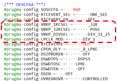
- Go to
MPLAB® Code
Configurator>Harmony>Clock
Configuration.
- Go to Clock Diagram in MCC.
- Set LPCLK source to SOSC. From the drop-down
list, select SOSC.
Figure 13-20. Manually Setting RTC Clock Source – SOSC 
Figure 13-21. SOSC Configuration bits Generated after Code Generation 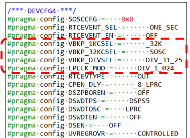
- Clock Switching mechanism , if LPCLK source is set as POSC clock source using clock configuration, the FW switch to LPRC as LPCLK source as POSC clock source is unavailable in Deep Sleep Low Power Mode.
Enabling Deep Sleep/Backup Low Power Mode
| Application Example | Description | Reference |
|---|---|---|
| BLE Deep Sleep Advertising | On reset, the device starts in Deep Sleep mode. Pressing the SW1 button on the curiosity board starts the system’s Deep Sleep Advertisements. Once a central device connects, the device switches to Sleep Low Power mode. | See BLE Deep Sleep Advertising from Related Links. |
Recommendations for Deep Sleep Advertisement Mode
Ensure to use Deep Sleep Advertisement mode when the advertisement interval is >= 500 ms.
Supported BLE Advertisement Types in Deep Sleep Mode
When using Deep Sleep mode, the system supports BLE legacy advertisement
types ADV_IND, ADV_SCAN_IND,
ADV_DIRECT_IND_LOW, and
ADV_NONCONN_IND.
Retaining Application Data in Backup RAM
The user must define the variable as persistent. Persistent variables are variables that the runtime start-up code must not clear, such as during a reset. The user must initialize a persistent variable as follows. The data read/write into backup RAM must be single word (4 bytes).
uint32_t __attribute__((persistent)) backup1;
The user firmware must not assign initial values for persistent variables.
Bootloader Firmware Authentication in Deep Sleep Mode
If firmware authentication is enabled in the bootloader, it checks for Firmware Authentication upon all types of resets like POR, BOR, and more. The device skips firmware authentication only when it wakes up from Deep Sleep Low Power mode.
Recommended RTC Clock Sources for Deep Sleep Mode
The recommendation is to use SOSC or LPRC as the clock sources when using the Deep Sleep mode.