
6.6.1.4 Dimmable Light control and Monitoring using Combined Interface (with Touch Control)
WBZ351 Curiosity Board
Devices (Device): | PIC32CX5109BZ31048(MCU) on WBZ351 module |
Peripherals (Used, On-Board): |CVD Touch GREEN LED | User Button| UART-USB Converter|
Introduction
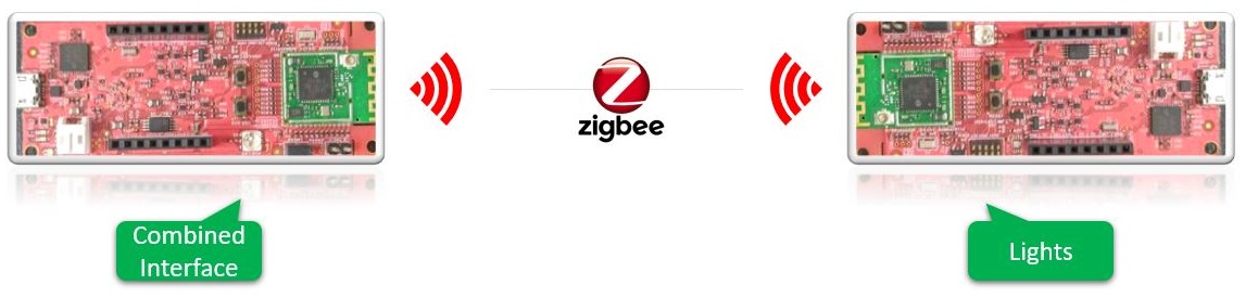
This page describes the demo steps for Light control and Monitoring using Combined Interface on WBZ351 Curiosity boards.An overview of the demo is shown below.
Hardware Required
| Tool | Qty |
|---|---|
| WBZ351 Curiosity Boards | 2 |
|
QT7 XPRO Extension Board |
1 |
| Micro USB cable | 2 |
| Personal Computer | 1 |
SDK Setup
Gettting Started with Software DevelopmentSoftware
TeraTermProgramming the precompiled hex file or Application Example
To run the demo , we need 2 devices. One is the Combined Interface and the other is dimmable light.
-
One of the WBZ351Curiosity board is programmed with Combined Interface which can act as Zigbee Gateway/Coordinator. Program the CI pre-compiled hex image by following steps on one curiosity board.
-
Another WBZ351 Curiosity board is programmed with Dimmable Light application which can act as Zigbee Router. Follow the below step for programming Dimmable Light application on another curiosity board.
Programming the hex file using MPLABX IPE
-
Precompiled Hex file is located in "<Harmony Content Path>\wireless_apps_pic32cxbz3_wbz35\apps\zigbee\dim_light_touch" folder
-
Follow the steps mentioned here
Caution: Users should choose the correct Device and Tool information
Programming the Application using MPLABX IDE
-
Follow steps mentioned in of Running a Precompiled Example document
-
Open and program the Application Example "dim_light_touch.x" located in "<Harmony Content Path>\wireless_apps_pic32cxbz3_wbz35\apps\zigbee\dim_light_touch\firmware" using MPLABX IDE
<Harmony Content Path> how to find what is my Harmony Content Path
Demo Description
The demo applications demonstrates the Zigbee protocol functionality of PIC32CXBZ/WBZ family of devices and modules. It consists of a ZigBee 3.0 Coordinator and Router implemented as shown below :
| Application | Zigbee Logical Device Type | Functionality |
|---|---|---|
| Combined Interface | Coordinator | Device capable of controlling and monitoring other devices. It is typically a mains-powered device like a personal computer |
| Dimmable Light | Router | Is a lighting device that can be switched on/off , brightness of the light can be adjusted via the color commands. In addition the light can be controlled using Touch button on QT7 XPRO extention board |
Zigbee device commissioning:
-
The Zigbee router i.e. Dimmable Lights can be commissioned and brought to the existing zigbee network formed by Zigbee coordinator i.e. Combined Interface or can create new zigbee Distributed network (if there is no nearby network).
Zigbee Light control:
-
Dimmable light GREEN LED can be controlled from Zigbee Gateway of the same network.
-
When the light status is changed the light change report will be sent to zigbee gateway through Zigbee communication.
Demo Steps:
The Zigbee light can be connected to any zigbee network.
Joining Light with WBZ351 Combined Interface (CI) Coordinator
- Supply power to WBZ351 Curiosity Board consisting of Combined
Interface application by connecting a USB cable. Power Supply (PS) Green LED
will turn on when connect to PC.
- The application activity is shown as "Console Log" through on board UART-USB converter
-
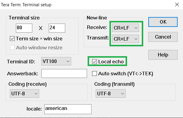
Open Terminal(eg: Tera Term) with the setup as shown below to look for these logs
-
On the PC side virtual COM port connection that corresponds to the board shall have following settings:
BAUD RATE: 115200 (as configured in SERCOM configuration)
PARITY: None
DATA BITS: 8
STOP BITS: 1
FLOW CONTROL: None
Network Formation (Coordinator - (Combined Interface))
Follow the steps explained in Network Formation (Coordinator - (Combined Interface)) to open up the network in CI.Commissioning (Router - Dimmable Light)
The Dimmable Lights can be connected to any zigbee gateway (Combined interface running on WBZ351 Curiosity Board in the previous step)-
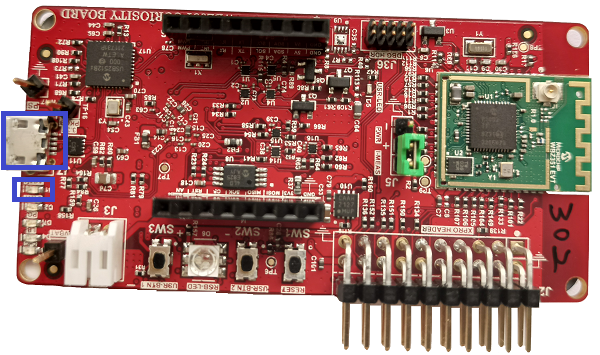
Supply power to WBZ351 Curiosity Board programmed with "Dimmable Light"
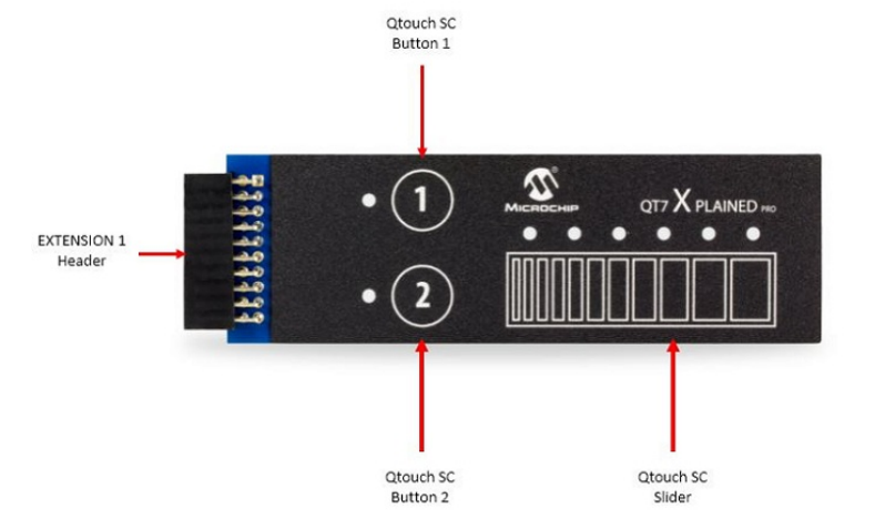
- Connect the QT7 Xplained Pro Extention
board on Curiosity board extention as shown.

- Supply power to by connecting a USB cable. Power Supply (PS) Green LED will turn on when connect to PC.
- Connect the QT7 Xplained Pro Extention
board on Curiosity board extention as shown.
-
Follow step 2 in "Hardware & Software Setup" for UART terminal Setup.
-
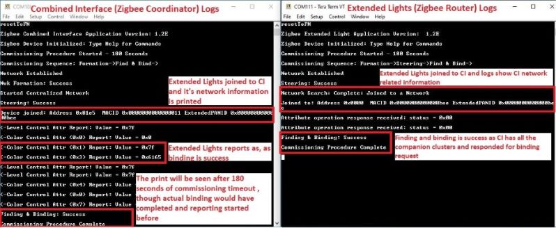
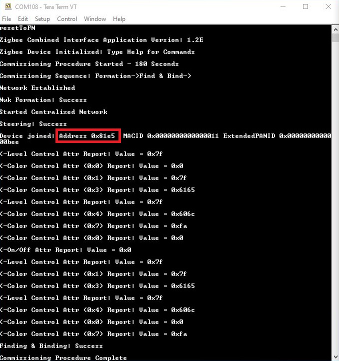
Input command : resetToFN and look for the below logs for successful joining with CI.
-
Success logs : When dimmable light successfully commissioned with Combined Interface below log will be seen.
Light Control
GREEN LED on WBZ351curiosity board is tied with Zigbee functionality. The LED brightness can be changed through Zigbee network .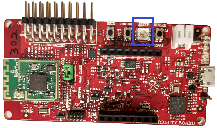
- The GREEN LED brightness can be controlled from Combined Interface through console commands.
- Brightness changed from Combined Interface, will be reflected in next received level control attribute report in combined Interface
- The network address of the light is needed to send light control commands to light.
- This network address can be got from Combined interface console log while commissioning was done. Refer to the above success log for light network address.
- Another way to get the network
address from light is executing the below command in light side.
Command: getNetworkAddress Response: f088 -
The table below shows few commands for light control(on /off, brightness). Refer to doc Serial Console Commands to get to know the different parameters of the commands.
| Command Type | Commands | Parameter Details |
|---|---|---|
| GREEN LED ON | onOff 0x0 0xf088 0x21 -on | 0x21 zigbee end-point number used for Dimmable Light |
| GREEN LED OFF | onOff 0x0 0xf088 0x21 -off | 0x21 zigbee end-point number used for Dimmable Light |
| GREEN LED brightness change | moveToLevel 0x0 0xf088 0x21 0x45 0x0 0x1 0x0 0x0 | 0x45 is the configurable brightness value |
-
Important:
If the QT7 XPRO board is not connected with WBZ351 curiosity board, by touching on curiosity board extention pins might cause the Touch detection. Hence Touch functionality is disabled by default.
To activate touch functionality , enable ENABLE_TOUCH macro command in the following file dim_light_touch\firmware\src\app.h

- Button 2 marked on QT7 XPRO board can switch On/Off the GREEN LED. Touch and release the Button 2. See the GREEN LED is On. A LED near to Button 2 will also glow.
- The Slider can help to increase/decrese the brightness of GREEN LED. The lowest position will bring the brightness Low, and highest slider position will bring the GREEN LED brighness to High. The brightness are in the scale of 0 to 255.
- Slide on the Touch slider and observe the GREEN LED brightness changes. The 6 LED's adjacent to Slider will also show the brightness level.
- Touch and release the Button 2 and observe that GREEN LED is Off. All the Touch
LED's also will be Off. Changing the slider position will not change the
brightness until the LED is On by Button 2.Note:The GREEN LED state and brightness change by Touch button will get reflected in light reports seen on Combined Interface.
-
On board button actions:
-
When the on board "User Button (SW3)" is pressed for more than 10sec, it can delete all the networking information and will bring the device to factory default state. This functionality is available in both combined interface and light devices.
-
-
Persistent Data Storage (PDS): The light status (On/Off) and brightness values are stored in non-volatile memory called PDS.
- Power off/on of dimmable light, these values persist and LED will reflect accordingly. This PDS storage is tied to zigbee network.
-
The light On/Off status and light brightness is being stored in non-volatile memory in this case. So, power off/on, the LED will be updated with light on/off and brightness values retrieved from previous transaction
Creating Application Device Types From Scratch Using MCC
All the supported device types including this Dimmable light projects can be generated by following the steps in Generating project from MCC.