
5.3 Power-Up/Down Sequence
The following figure illustrates the power-up/down sequence for the ATWINC3400-MR210xA.
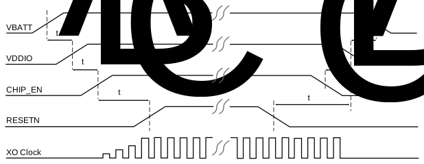
The following table provides power-up/down sequence timing parameters.
| Parameter | Min. | Max. | Units | Description | Notes |
|---|---|---|---|---|---|
| tA | 0 | — | ms | VBAT rise to VDDIO rise | VBAT and VDDIO can rise simultaneously or connected together. VDDIO must not rise before VBAT. |
| tB | 0 | — | ms | VDDIO rise to CHIP_EN rise | CHIP_EN must not rise before VDDIO. CHIP_EN must be driven high or low and must not be left floating. |
| tC | 5 | — | ms | CHIP_EN rise to RESETN rise | This delay is required to stabilize the XO clock before RESETN removal. RESETN must be driven high or low and must not be left floating. |
| tA’ | 0 | — | ms | VDDIO fall to VBAT fall | VBAT and VDDIO must fall simultaneously or be connected together. VBAT must not fall before VDDIO. |
| tB’ | 0 | — | ms | CHIP_EN fall to VDDIO fall | VDDIO must not fall before CHIP_EN. CHIP_EN and RESETN must fall simultaneously. |
| tC’ | 0 | — | ms | RESETN fall to VDDIO fall | VDDIO must not fall before RESETN. RESETN and CHIP_EN fall simultaneously. |