
10.4.1 I2C Client Timing
The I2C Client timing diagram for the ATWINC3400-MR210xA module is shown in the following figure.
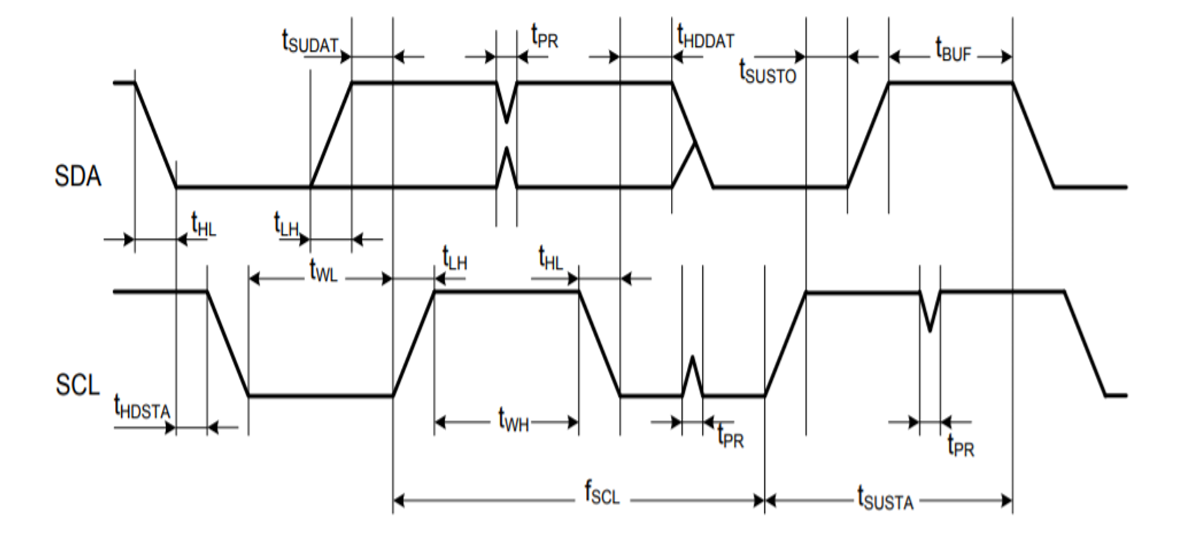
The following table provides the I2C Client timing parameters for the ATWINC3400-MR210xA module.
| Parameter | Symbol | Min. | Max. | Units | Remarks |
|---|---|---|---|---|---|
| SCL Clock Frequency | fSCL | 0 | 400 | kHz | — |
| SCL Low Pulse Width | tWL | 1.3 | — | µs | — |
| SCL High Pulse Width | tWH | 0.6 | — | — | |
| SCL, SDA Fall Time | tHL | — | 300 | ns | — |
| SCL, SDA Rise Time | tLH | — | 300 | This is dictated by external components | |
| START Setup Time | tSUSTA | 0.6 | — | µs | — |
| START Hold Time | tHDSTA | 0.6 | — | — | |
| SDA Setup Time | tSUDAT | 100 | — | ns | — |
| SDA Hold Time | tHDDAT | 0 | — | ns | Client and Host Default |
| 40 | — | µs | Host Programming Option | ||
| STOP Setup Time | tSUSTO | 0.6 | — | µs | — |
| Bus Free Time Between STOP and START | tBUF | 1.3 | — | — | |
| Glitch Pulse Reject | tPR | 0 | 50 | ns | — |