In MCC, the Clock Diagram tab shows all the clocks available in the PIC32MZ1025W104 SoC and their configuration options. The permitted range of inputs is set to generate clock configurations for a pre-determined output range (via drop-down menus). Use the clock diagram for the following purposes:
Note: Use only to override defaults; usually not recommended.
To configure any clock PLL in the PIC32MZ W1 family if needed
To reconfigure peripheral clock dividers if needed for a particular use case
Figure 2-4. Launch Clock Diagram
The following table lists the clock sources for all the peripherals supported by the PIC32MZ W1 family.
Table 2-4. Clock Sources for PIC32MZ W1 Peripherals
PLL
Peripheral CLK
Peripherals
SPLL
PBCLK5
TRNG, BA414E, Symmetric Crypto
PBCLK3
Ethernet, I2C2, ICAP-1/2/3/4, SQI1, OCMP-1/2/3/4, UART-1/2, SPI-1/2, USB
BOR, NVM, WDT, DMT, PPS, PTG, UART3, Timer 1-7, CFG
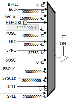
Route each PLL to inputs on the clock MUX and configure as a system clock source as shown in the following figure. Microchip recommends using SPLL to generate the system clock (through ROSEL1). The following figure shows the actual values used in this release.Figure 2-5. PLL Clock Source Selection
By default, the system is set to operate at a maximum frequency of 200 MHz. All the software demos are tested at this frequency. The following table lists the different clock frequencies supported by the PIC32MZ W1 family.
Table 2-5. Clock Frequencies
Clock
Frequency (MHz)
ETHCLK
50
EWPLL
160
UPLL
96
The FRC (8 MHz) is a low-frequency clock available at boot-up as the system clock until the user switches to other clock sources during initialization.
DS50003034B
The online versions of the documents are provided as a courtesy. Verify all content and data in the device’s PDF documentation found on the device product page.