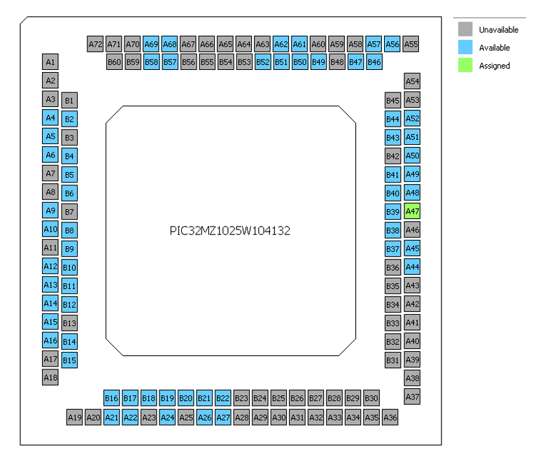
The Pin Manager enables users to configure (assign peripheral function, set pin direction, configure pull-up or pull-down, and so on) and map the I/O pins. It consists of Pin Settings, Pin Diagram, and the Pin Table tabs. The following figure illustrates the pictorial representation of the available, assigned, and not available pins of the MCU. Figure 2-9. Pin Diagram
Note: The following color combinations are associated with the pins in the graphical or table view:
Gray – These pins are not used in the selected configuration. These pins are locked out by selected system functions and cannot be changed by the user.
Green – This pin is allocated and selected for a module. It displays either the name of the pin in the module’s context or a custom name entered. This pin is locked and not available for any new pin assignment.
Pin: A47.
The Pin Table tab provides the Pin Manager’s grid view. Select DQFN from the Package drop-down list.
The package details display in the package view.
The table view provides the pin numbers for the selected package. The leftmost columns in the table view indicate the module and the functionality name.
The grid cells indicate the status of a pin for a specific function.
Available (Blue): The function can be assigned to this pin.
Assigned (Green): The function is currently allocated to this pin.
Unavailable/Locked (Gray): The function cannot be assigned to this pin due to a conflict or hardware limitation.
Unselected (White/Clear): No assignment has been made.
Figure 2-10. Pin Table
The Pin Settings tab enables the user to perform the following functions:
To configure the pins
To provide a custom name for the pin
To change the pin function, direction, latch and other properties
Figure 2-11. Pin Settings
The following figure illustrates an example where the RA11 pin is configured as an U2TX (UART2 transmit pin). Similarly, it shows another example where the RA13 pin is configured as a GPIO. The highlighted buttons on the right side enable the user to set the Direction, Latch, and Mode of the selected pin.
The online versions of the documents are provided as a courtesy. Verify all content and data in the device’s PDF documentation found on the device product page.