
2.2.2.1 Clock Configuration Procedure
Perform the following steps to configure PLLs and peripheral clocks for recommended values:
- Launch the MCC configuration menu for the main project.
- Open the
Clock Diagram from the menu as shown in Clock Source Selection.Note: The sample applications are pre-configured with these values by default.
- Enable POSCMOD to HS (if not set).
Figure 2-6. Enable POSCMOD 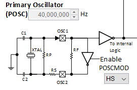
- Select the input clock as POSC from the respective clock MUX for SPLLICLK and EWICLK as shown in the following figure.
- Click the Auto-Calculate button for each PLL block to set the proper divisor values to achieve the required output frequency.
- In all the example codes, the system
clock (SYSCLK) is set to 200 MHz.
Figure 2-7. Set Input Voltage 
Note: The following instructions are for specific use cases, where the configuration may need a modification. Generally, these configurations are done by default by Harmony and do not require a change for most of the cases. - Enable POSCMOD to HS (if not set).
- Generate the
peripheral clock (PBCLK1) as per the following requirements:
- Ensure from the Clock Diagram that the required frequencies are derived for peripheral clocks through the clock settings. Most of the peripheral clocks are SYSCLCK/2.
- Some applications may need to use 4 as
the PBCLK3 divisor value (PB3DIV) to provide a 50 MHz clock for the required
peripherals.
Figure 2-8. PBCLK3 Divisor Value 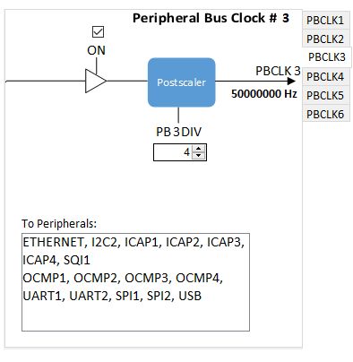
- Save the
settings and click on the
 button to generate the code.
- Once the code generation is successful, click on the Build Project button.
- The “Build Successful” message in the output window of MPLAB X IDE confirms successful compilation.
Note: This procedure applies to all the
existing examples or demo projects and for the development of new examples or application
projects.