6 Space Vector Pulse Width Modulation (SVPWM)
The final step in the vector control process is to derive pulse-width modulation signals for the inverter switches to generate 3-phase motor voltages. If the Space Vector Modulation (SVPWM) technique is used, the process of generating the PWM is reduced to a few simple equations. In this implementation, the Inverse Clarke Transform is folded into the SVM routine, which further simplifies the calculations.
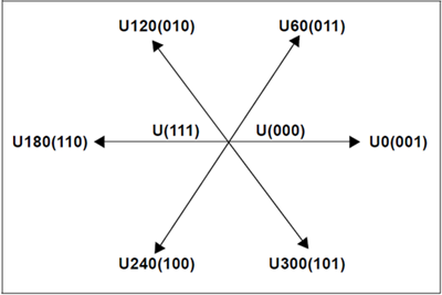
Each of the three inverter outputs can be in one of the two states. The inverter output can be connected to either the plus (+) bus rail or the minus (-) bus rail, which allows for 23 = 8 possible states of the output.
The two states in which all three outputs are connected to either the plus (+) bus or the minus (-) bus are considered null states because there is no line-to-line voltage across any of the phases. These are plotted at the origin of the SVM star. The remaining six states are represented as vectors with a 60 degree phase difference between adjacent states as shown in the following figure.
The process of SVPWM allows for the representation of any resultant vector by the sum of the components of the two adjacent vectors. For example, in the following figure, UOUT is the desired resultant. It lies in the sector between U60 and U0. If during a given PWM period 'T', U0 is applied for time T1 and U60 is output for time T2, the resulting voltage for the period T will be UOUT.
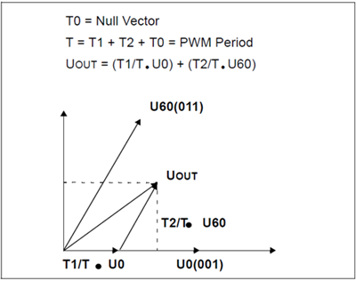
T0 represents a time when no effective voltage is applied to the windings, that is, where a null vector is applied. The values for T1 and T2 can be extracted with no extra calculations by using a modified Inverse Clark transformation. If Vα and Vβ are reversed, a reference axis for SVM is generated which is shifted by 30 degrees from the SVM star as shown in the following figure. The timings of the voltage vectors along those two axes that bind the sector are equal to T1 and T2. The null vectors are applied in the remaining time T0 of the switching period T.
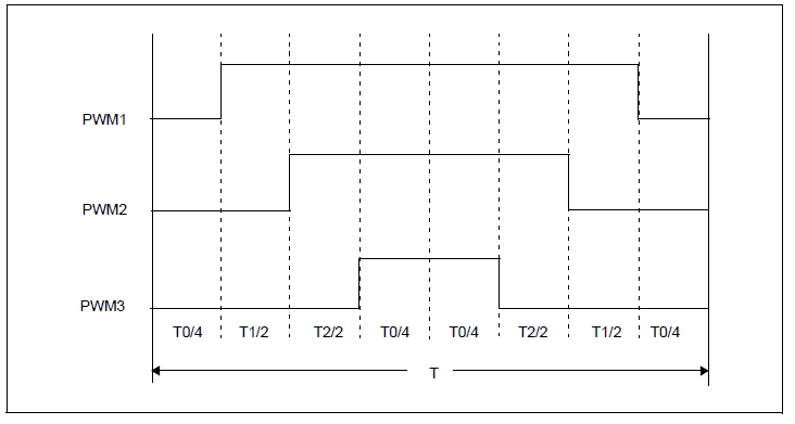
The construction of the symmetrical pulse pattern can be seen in the following figure, which produces minimum output harmonics.