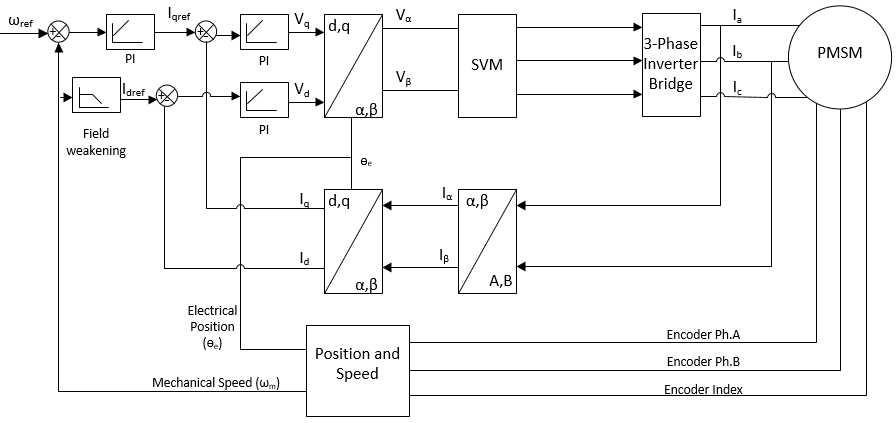
2 Block Diagram of Sensored FOC of PMSM
The control can be summarized as follows:
- The three-phase stator currents are
measured. For a motor with balanced three-phase windings, only two currents are
sufficient to be measured. The third current can be calculated by the following
equation:
- The three-phase currents are converted to a stationary two-axis system. This conversion provides the variables iα and iβ from the measured ia, ib, ic values. The values iα, iβ are time-varying quadrature current values as viewed from the perspective of the stator.
- The stationary two-axis coordinate system is rotated to align with the rotor flux using a transformation angle measured at the last iteration of the control loop. This conversion provides the id, iq variables from iα and iβ. The values id and iq are the quadrature currents transformed to the rotating coordinate system. For steady state conditions, id, iq are constant.
- Reference values of currents are explained below:
- id reference: controls rotor magnetizing flux
- iqreference: controls the torque output of the motor
- The error signals are fed to PI controllers. The output of the controllers provide vd, vq, which are voltage vectors that will be applied to the motor.
- A new transformation angle is measured from the encoder pulses input. This new angle guides the FOC algorithm as to where to place the next voltage vector.
- The vd, vq output values from the PI controllers are rotated back to the stationary reference frame using the new angle. This calculation provides the next quadrature voltage values vα,vβ.
- The vα,vβ values are used to calculate the new PWM duty cycle values which will generate the desired voltage vector
- Mechanical speed (ωm) is calculated after every discrete PWM cycle
The FOC software is implemented in the ADC interrupt service routine after the end of the conversion of data. It runs at the same rate as the PWM switching frequency.
Field Oriented control of PMSM in the form of a block diagram is shown in the following figure.