1.3 ADCHS Interrupt
This example application shows how to sample an analog input using the ADCHS peripheral and display the converted samples on a serial terminal.
Description
In this application, an analog input is converted by a software edge trigger. Converted digital value is displayed on the serial terminal.
Downloading and Building the Application
To clone or download this application from Github, go to the main page of this repository and then click Clone button to clone this repository or download as zip file.
Path of the application within the repository is apps/adchs/adchs_interrupt.
To build the application, refer to the following table and open the project using its IDE.
| Project Name | Description |
|---|---|
| pic32wm_bw1_curiosity.X | MPLAB X project for PIC32WM-BW1 Curiosity board |
Setting Up the Hardware
The following table shows the target hardware for the application projects.
| Project Name | Board |
|---|---|
| pic32wm_bw1_curiosity.X | PIC32WM-BW1 Curiosity board |
Setting Up PIC32WM-BW1 Curiosity Board
- Connect the AN5 pin RB1 (Pin 2 of the J8 connector) to the VCC (or GND)
- Connect the USB port on the board to the computer using a USB Type-C cable
Running the Application
- Open the Terminal application (E.g., Tera term) on the computer.
- Connect to the USB COM port and
configure the serial settings as follows:
- Baud : 115200
- Data : 8 Bits
- Parity : None
- Stop : 1 Bit
- Flow Control : None
- Build and program the application project using its IDE.
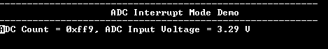
- Console displays the ADC count
and the ADC input voltage.