1.4 CCL Manchester Encoder
This example application shows how to use the CCL peripheral library and generate a Manchester-encoded output.
Description
This demonstrates a way to generate a Manchester-encoded output using a SPI port and the CCL. The SPI port is sending out a predefined buffer of data in a circular fashion. Data is sent out LSB first, with CCL_OUT being the Manchester-encoded output. The pins are configured such that a logic analyzer can be attached to see the input (MOSI and SCK) and the output (CCL_OUT) simultaneously.
Downloading and Building the Application
To clone or download this application from Github, go to the main page of this repository and then click Clone button to clone this repository or download as zip file.
Path of the application within the repository is apps/ccl/manchester_encoder.
To build the application, refer to the following table and open the project using its IDE.
| Project Name | Description |
|---|---|
| pic32wm_bw1_curiosity.X | MPLAB X project for PIC32WM-BW1 Curiosity board |
Setting Up the Hardware
The following table shows the target hardware for the application projects.
| Project Name | Board |
|---|---|
| pic32wm_bw1_curiosity.X | PIC32WM-BW1 Curiosity board |
Setting Up PIC32WM-BW1 Curiosity Board
- Use jumper from RA8 (Pin 12 of XPRO Header 1) to Pin 2 of J8 connector (This routes SCK signal to CCLIN1)
- RA7 (Pin 11 of XPRO Header 1) has MOSI output
- RB2 (Pin 4 of XPRO Header 1) has CCL output (CCL_OUT0)
- Connect the USB port on the board to the computer using a USB Type-C cable
Running the Application
- Connect a logic analyzer to MOSI pin.
- Connect a logic analyzer to SCK pin.
- Connect a logic analyzer to the Manchester-encoded output CCL_OUT pin.
- Refer to the following table for pin details:
Board MOSI Pin SCK Pin CCL_OUT Pin PIC32WM-BW1 Curiosity board RA7 RA8 RB2 (Pin 4 on XPRO Header 1) - Build and program the application using its IDE.
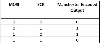
- Observe the output on logic
analyzer, it should follow the truth table as shown in the following
diagram.