
1.14 RTC Alarm Interrupt
This example shows how to use the RTC to configure the time and generate the alarm.
Description
This example application shows how to setup system time and configures alarm using the RTC peripheral library. The application sets up an alarm to be generated after 20 seconds of the configured system time. The application displays a message on the alarm trigger.
Downloading and Building the Application
To clone or download this application from Github, go to the main page of this repository and then click Clone button to clone this repository or download as zip file.
Path of the application within the repository is apps/rtc/rtc_alarm.
To build the application, refer to the following table and open the project using its IDE.
| Project Name | Description |
|---|---|
| pic32wm_bw1_curiosity.X | MPLAB X project for PIC32WM-BW1 Curiosity board |
Setting Up the Hardware
The following table shows the target hardware for the application projects.
| Project Name | Board |
|---|---|
| pic32wm_bw1_curiosity.X | PIC32WM-BW1 Curiosity board |
Setting Up PIC32WM-BW1 Curiosity Board
- Connect the USB port on the board to the computer using a USB Type-C cable
Running the Application
- Open the Terminal application (E.g., Tera term) on the computer.
- Connect to the USB port and
configure the serial settings as follows:
- Baud : 115200
- Data : 8 Bits
- Parity : None
- Stop : 1 Bit
- Flow Control : None
- Build and program the application project using its IDE.
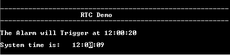
- The console displays the current
time and the alarm time (system time starts at 12:00:00 and gets updated every
second).
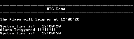
- Once the alarm time is reached,
it prints the alarm message and turns on the LED (system time keeps
updating).
Refer to the following table for LED name:
| Board | LED Name |
|---|---|
| PIC32WM-BW1 Curiosity board | Green LED |