1.16 TCP/IP UDP Server
The UDP Server configuration demonstrates creating a network server that uses the MPLAB Harmony UDP API to create a UDP/IP echo server on port 9760.
TCP/IP UDP Server MCC Configuration
The following Project Graph diagram shows the Harmony components included in the UDP Server application demonstration.
MCC is launched by selecting Tools > Embedded > MPLAB® Code Configurator from the MPLAB X IDE and after opening the project, TCP/IP demo project is ready to be configured and regenerated.
TCP/IP Root Layer Project Graph
The root layer project shows that UART2 peripheral is selected to do read and write operation for TCP/IP commands.
This is the basic configuration with SYS_CONSOLE, SYS_DEBUG and SYS_COMMAND modules. These modules are required for TCP/IP command execution.
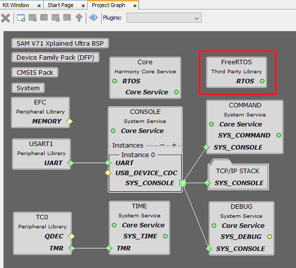
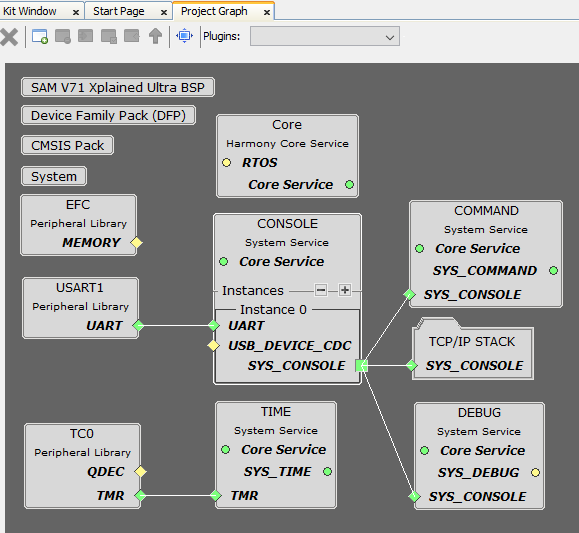
FreeRTOS component is required for RTOS application. For bare-metal (non-RTOS) FreeRTOS component should not be selected.
NOTE - The above diagram contains FreeRTOS component and that is required for RTOS application. For bare-metal(non-RTOS) FreeRTOS component shouldn't be selected.
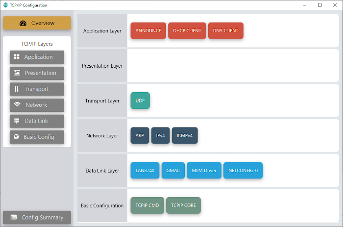
TCP/IP Configuration
SAM E70 Xplained Ultra
SAM V71 Xplained Ultra

TCP/IP Required Application
TCP/IP demo use these application module components for this demo.
Announce module to discover the Microchip devices within a local network.
DHCP Client module to discover the IPv4 address from the nearest DHCP Server.
DNS Client provides DNS resolution capabilities to the stack. During these components selection, the required transport and network modules are also selected.
TCPIP Data Link Layer
Internal ethernet driver(gmac) is enabled with the external LAN8740 PHY driver library for SAME70 demonstartion.
For SAM V71 demonstration , LAN8061 PHY driver ia selcted along with GMAC Internal ethernet driver.
The MIIM Driver supports asynchronous read/write and scan operations for accessing the external PHY registers and notification when MIIM operations have completed.
TCP/IP UDP Client Hardware Configuration
This section describes the hardware configuration for ATSAM E70/V71 Xplained Ultra Evaluation Kit and one can be used for the respective application demonstration.
This section describes the required default hardware configuration use SAM E70 Xplained Ultra Evaluation Kit
Ensure ERASE jumper is Open.
Open the J805 Jumper
Refer to the SAM E70 Xplained Ultra User Guide
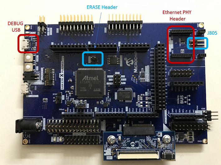
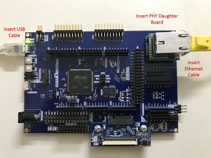
Insert the LAN8740 PHY daughter board on the ETHERNET PHY MODULE header.
Connect the micro USB cable from the computer to the DEBUG USB connector on the SAM E70 Xplained Ultra Evaluation Kit
Establish a connection between the router/switch with the SAM E70 Xplained Ultra Evaluation Kit through the RJ45 connector
This section describes the required default hardware configuration use SAM V71 Xplained Ultra Evaluation Kit
No hardware related configuration or jumper setting changes are necessary
Ensure ERASE jumper is Open
Refer to the SAM V71 Xplained Ultra User Guide
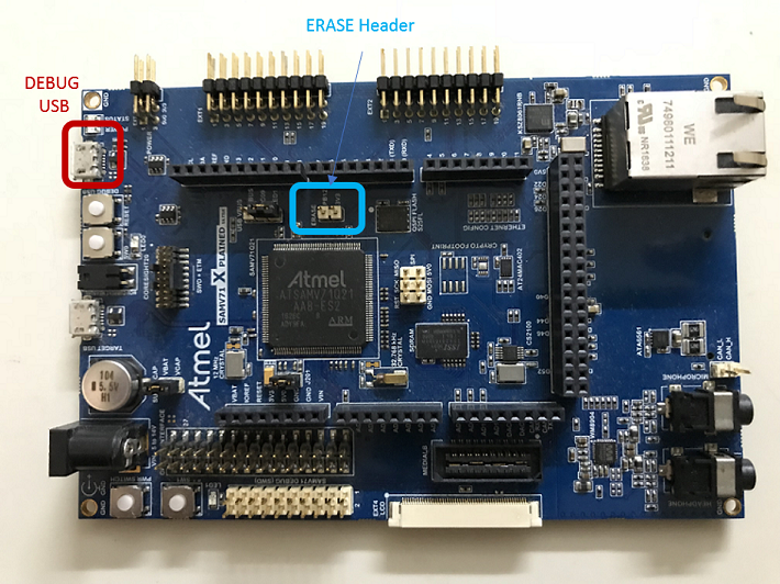
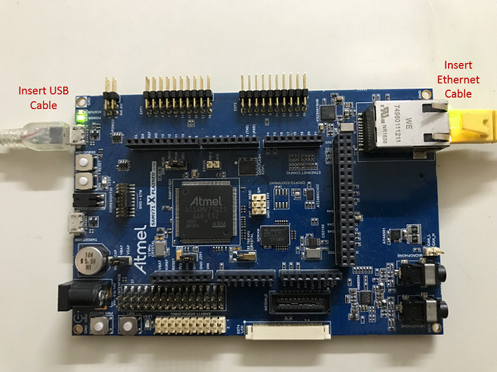
Connect the micro USB cable from the computer to the DEBUG USB connector on the SAM V71 Xplained Ultra Evaluation Kit
Establish a connection between the router/switch with the SAM V71 Xplained Ultra Evaluation Kit through the RJ45 connector
TCP/IP UDP Server Running Application
This table list the name and location of the MPLAB X IDE project folder for the demonstration.
| Project Name | Target Device | Target Development Board | Description |
|---|---|---|---|
| sam_e70_xult.X | ATSAME70Q21B | SAME70 Xplained Ultra + LAN8740 PHY Daughter board | Demonstrates the UDP Server on development board with ATSAME70Q21B device and LAN8740 PHY daughter board. This implementation is based on Bare Metal ( non-RTOS). |
| sam_e70_xult_freertos.X | ATSAME70Q21B | SAME70 Xplained Ultra + LAN8740 PHY Daughter board | Demonstrates the UDP Server on development board with ATSAME70Q21B device and LAN8740 PHY daughter board. This implementation is based on Freertos. |
| sam_v71_xult.X | ATSAMV71Q21B | SAMV71 Xplained Ultra | Demonstrates the UDP Server on development board with ATSAMV71Q21B device and KSZ8061 PHY daughter board. This implementation is based on Bare Metal (non-RTOS). |
| sam_v71_xult_freertos.X | ATSAMV71Q21B | SAME70 Xplained Ultra | Demonstrates the UDP Server on development board with ATSAMV71Q21B device and KSZ8061 PHY daughter board. This implementation is based on Freertos. |
Running Demonstration Steps
Build and download the demonstration project on the target board.
If the board has a UART connection:
A virtual COM port will be detected on the computer, when the USB cable is connected to USB-UART connector.
Open a standard terminal application on the computer (like Hyper-terminal or Tera Term) and configure the virtual COM port.
Set the serial baud rate to 115200 baud in the terminal application.
See that the initialization prints on the serial port terminal.
When the DHCP client is enabled in the demonstration, wait for the DHCP server to assign an IP address for the development board. This will be printed on the serial port terminal.
Alternatively: Use the Announce service or ping to get the IP address of the board.
Run tcpip_discoverer.jar to discover the IPv4 and IPv6 address for the board.
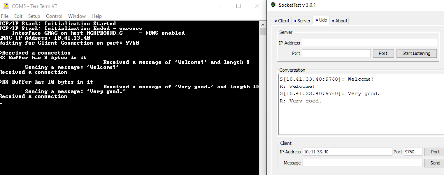
Execution:
After the successful board bring up, the console output becomes
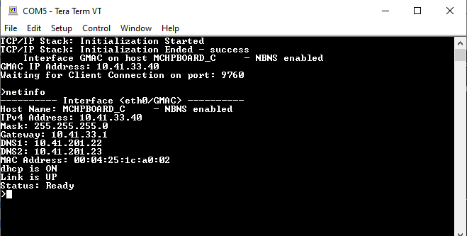
As soon as a valid IP address is assigned through the DHCP to the demonstration, it is ready to accept a UDP/IP connection on port 9760.
Send a UDP packet to the IP address of the hardware board and port 9760 from any UDP Client application running on the computer.