
20.2.2.3.10 Physical Memory Protection
(Ask a Question)The Physical Memory Protection (PMP) prevents a process (running on a RISC-V Processor) or an initiator (FPGA Fabric) from accessing memory that has not been allocated to it. RISC-V system has PMP unit, which provides control registers for each processor to allow physical memory access privileges (read, write, execute) to be specified for each physical memory region.
For more information on how PMP works on RISC-V® processors, refer the RISC-V PMP - With PFSoC Examples page.
Similarly, the AXI Switch has Memory Protection Unit (MPU) block which provides register control to setup memory access regions for FPGA initiators.
Application Processor Initialization
The following figure shows the Application Processor Initialization tab.


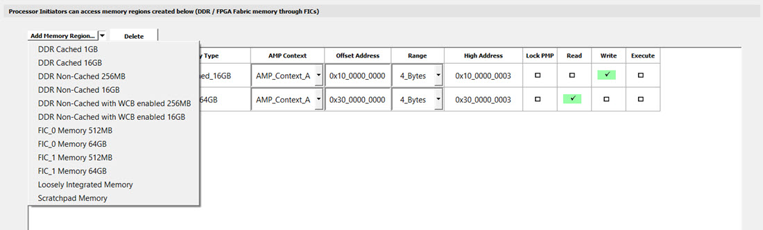
| Memory Type | Memory Size | Address Size | Address Range |
|---|---|---|---|
| DDR Cached | 512 MB | 32-bit | 0x80000000 - 0xBFFFFFFF |
| 16 GB | 64-bit | 0x10_00000000 - 0x13_FFFFFFFF | |
| DDR Non-Cached | 256 MB |
32-bit | 0xC0000000 - 0xCFFFFFFF |
| 16 GB | 64-bit | 0x14_00000000 - 0x17_FFFFFFFF | |
| DDR Non-Cached with WCB enabled | 256 MB | 32-bit | 0xC0000000 - 0xCFFFFFFF |
| 16 GB | 64-bit | 0x14_00000000 - 0x17_FFFFFFFF | |
| FIC_0 Memory | 512 MB | 32-bit | 0x60000000 - 0x7FFFFFFF |
| 64 GB | 64-bit | 0x20_00000000 - 0x2F_FFFFFFFF | |
| FIC_1 Memory | 512 MB | 32-bit | 0xE0000000 - 0xFFFFFFFF |
| 64 GB | 64-bit | 0x30_00000000 - 0x3F_FFFFFFFF | |
| Loosely Integrated Memory | — | — | Start Address is 0x0800_0000 |
| Scratch | — | — | Start Address is 0x0A00_0000 |
When the values are modified for Peripherals and Memory Regions, the same gets updated dynamically in the PMPxCFG and CSRPMP_ADDx pairs in both the Context A and Context B tables.
The Monitor Processor Initialization view has a Monitor Processor Initialization tab with a default region, E51_Memory_Region_0. It can only be modified in the Expert Mode.
The following figure shows the Monitor Processor Initialization tab.

Direct Memory Access

|
Memory Type |
Memory Size |
Address Size |
Address Range |
|---|---|---|---|
| DDR Non-Cached |
256 MB |
32-bit | 0xC0000000 - 0xCFFFFFFF |
|
16 GB | 64-bit | 0x14_00000000 - 0x17_FFFFFFFF | |
|
FIC_0 Memory |
512 MB | 32-bit | 0x60000000 - 0x7FFFFFFF |
|
64 GB | 64-bit | 0x20_00000000 - 0x2F_FFFFFFFF | |
| FIC_1 Memory |
512 MB | 32-bit | 0xE0000000 - 0xFFFFFFFF |
|
64 GB | 64-bit | 0x30_00000000 - 0x3F_FFFFFFFF | |
|
FIC_3 Memory |
512 MB |
32-bit |
0x40000000 - 0x5FFFFFFF |
|
User Crypto Memory |
128 KB |
32-bit |
0x22000000 - 0x2201FFFF |
Expert Mode
Expert Mode is a specialized feature in the configurator intended for advanced users who require direct control over PMP and MPU configurations. It allows manual modification of these settings, overriding the automatic updates and calculations normally performed by the application. However, the Peripherals and Memory Regions tables do not update dynamically in this mode, nor can they be edited.
Expert Mode is applicable for the Application Processor Initialization, Monitor Processor Initialization and DMA tabs.
The following figure shows the Expert Mode in use in the Application Processor Initialization tab.

When the Expert Mode is disabled, all changes made are discarded and the values from the latest entries in the Initiator tables are displayed.