
CMOS, HCMOS, and LVCMOS
CMOS is an acronym for Complementary Metal Oxide Semiconductor, which means that the device (buffer) has been constructed of both P-channel and N-channel transistors.
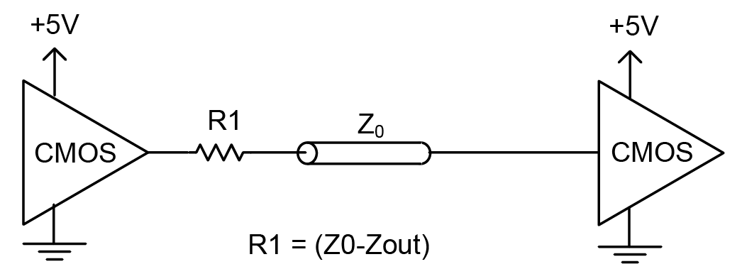
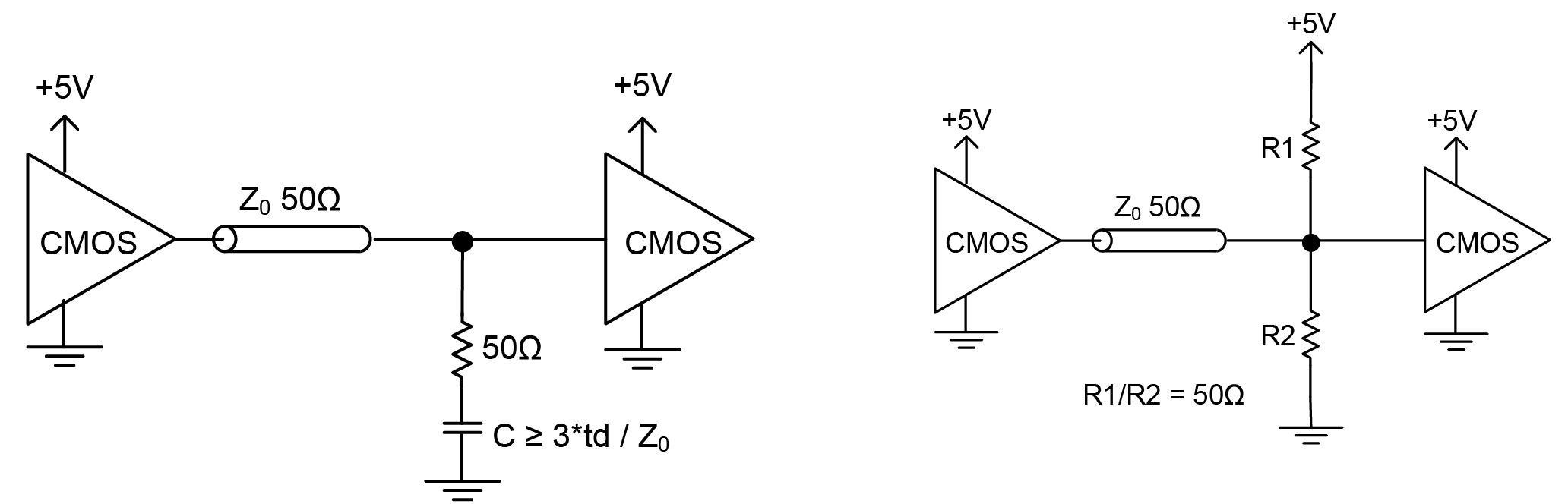
CMOS signals are distributed across a backplane, that has 50Ω impedance traces, into one or more high impedance receivers. As such, there is an impedance mismatch. There are ways to deal with this impedance mismatch, but between this and the inherit limits of the “rail to rail” swing, CMOS outputs are suitable for lower frequency clock sources (below 200MHz) and shorter trace lengths (less than one-fourth the wavelength of the highest harmonic frequency) that are less susceptible to impedance matching issues. For lower frequencies and short traces, a direct connection between the clock output and the receiver’s input can be used. However, in most cases, a low value (e.g., 20Ω to 50Ω) series resistor is used and is quite effective in reducing reflections and maintaining signal integrity. See Figure . Other methods for impedance matching are shown in Figure , but these increase power consumption.
HCMOS stands for High Speed CMOS and is a higher speed variant on the original CMOS; the terms HCMOS and CMOS are often interchangeable in the oscillator world. LVCMOS stands for Low Voltage CMOS and, as its name suggests, it is a low voltage class of CMOS. ACMOS stands for “Advanced CMOS”. As these acronyms are often used interchangeably, Microchip suggests specifying an oscillator using rise/fall time, output drive or load requirements, and VOH/VOL as opposed to defining the requirements by the terms CMOS, HCMOS, ACMOS, LVCMOS, etc.