
1.2.5.8.1 Abstraction Model
To understand how this library works you must first understand how an external Ethernet PHY interfaces with the Ethernet Controller. As shown in Figure 1, the PHY has two interfaces:
The management interface for configuration/control of the PHY, known as the Media Independent Interface Management (MIIM) or Serial Management Interface (SMI)
The transmit and receive data interface, which could be the Media Independent Interface (MIIM) or the Reduced Media Independent Interface (RMII)
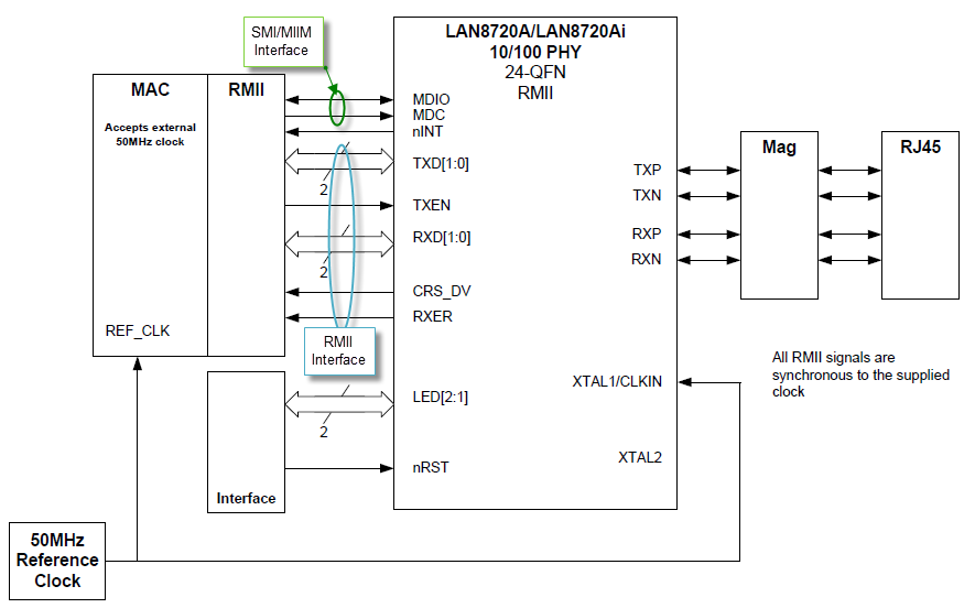
The block diagram also shows an interrupt signal (nINT) going to an external interrupt pin on the host device and signals going to on-board LEDs to show link state and link activity.
The SMI or MIIM interface controls the PHY. This control interface is standardized for all PHYs by Clause 22 of the 802.3 standard. It provides up to 32 16-bit registers on the PHY. The following table provides a summary of all 32 registers. Consult the data sheet for the PHY device for the specific bit fields in each register.
| Register Address | Register Name | Register Type |
|---|---|---|
| 0 | Control | Basic |
| 1 | Status | Basic |
| 2,3 | PHY Identifier | Extended |
| 4 | Auto-Negotiation Advertisement | Extended |
| 5 | Auto-Negotiation Link Partner Base Page Ability | Extended |
| 6 | Auto-Negotiation Expansion | Extended |
| 7 | Auto-Negotiation Next Page Transmit | Extended |
| 8 | Auto-Negotiation Link Partner Received Next Page | Extended |
| 9 | HOST-CLIENT Control Register | Extended |
| 10 | HOST-CLIENT Status Register | Extended |
| 11-14 | Reserved | Extended |
| 15 | Extended Status | Extended |
| 16-31 | Vendor Specific | Extended |