
3.1.3.1 Smart Wireless Thermostat BLE Peripheral Application on PIC32CM LS60 Curiosity Pro Evaluation Kit
Description
This application operates as a GATT server using the RNBD451 BLE module. It periodically collects temperature data from the IO/1 Xplained Pro board and updates the temperature characteristic value whenever the temperature changes. The node waits for the connection request from the central node. Once connected, it sends temperature data in response to read requests from the GATT client(central node) and can receive and implement threshold limit values from the central node. An onboard LED turns on whenever the current temperature exceeds the designated limit.
Modules/Technology Used
-
Peripheral Modules (Secure)
- EVSYS
- NVMCTRL
- PM
- RTC
-
Peripheral Modules (Non- Secure)
- ADC
- SERCOM 2 (UART)
- SERCOM 3 (UART)
- SERCOM 5 (I2C)
- TC
-
System Services
- Time
-
Wireless driver
- RNBD BLE driver
-
Harmony Core Service

Hardware Used
Software/Tools Used
The projects have been verified to work with the following versions of software tools:
- For peripheral PIC32CM_LS60 BLE GATT server, refer to the Secure Project Manifest and Non-Secure Project Manifest of Secure and Non-Secure projects respectively
- MPLAB® X IDE v6.20
- MPLAB® XC32 C/C++ Compiler v4.45
- Tera term or any serial console application
Due to Microchip regularly updates tools, occasionally issue(s) could be discovered while using the newer versions of the tools. If the project does not seem to work and version incompatibility is suspected. It is recommended to double-check and use the same versions that the project was tested with. To download original version of MPLAB Harmony v3 packages, refer to the document How to Use the MPLAB Harmony v3 Project Manifest Feature (DS90003305).
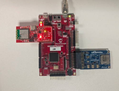
Hardware Setup
PIC32CM LS60 Thermostat Peripheral Node 1
-
Connect the RNBD Add-on board to the mikroBUS header on the PIC32CM LS60 Curiosity Pro evaluation kit
-
Ensure the jumper J2 of the RNBD451 Add-on board has the cap mounted between J(2-1) and J(2-2) to be powered by the mikroBUS header
-
Connect the I/O1 Xplained Pro Extension kit to the EXT2 in the PIC32CM LS60 Curiosity Pro evaluation kit
-
Connect the PIC32CM LS60 Curiosity Pro evaluation kit to the host PC as a USB device through a Type-A male to Micro-B USB cable connected to Micro-B USB (Debug USB) port

Programming Prebuilt Hex File
-
Open MPLAB X IDE
-
Close all existing projects in MPLAB X IDE, if any project is opened
- Go to File>Import>Hex/ELF file
- In the Import Image File
window,
- Create Prebuilt
Project,
- Click the Browse button to select the prebuilt hex file
- Select Device as PIC32CM5164LS60100
- Ensure the proper tool is selected under Hardware Tool and click the Next button
- Select Project Name
and Folder,
- Select appropriate project name and folder and click the Finish button
- Create Prebuilt
Project,
-
In MPLAB X IDE, click the Make and Program Device button to program the device
-
Follow the steps in Running the Demo section
Programming/Debugging Application Project
-
Open the project
ls60_cprogroupfrompic32cz_ca90_wireless_thermostat/firmware/pic32cm_ls60_cpro_wt_node1in MPLAB X IDE -
Open both Secure and Nonsecure projects inside the project group and set the Nonsecure as the main project
-
Ensure
PIC32CM LS60 Curiosity Prois selected as hardware tool to program/debug the application -
Build the code and program the device by clicking on the Make and Program button in MPLAB X IDE tool bar
-
Follow the steps in Running the Demo section
Running the Demo
PIC32CM LS60 BLE Peripheral Node
-
Power up the board
-
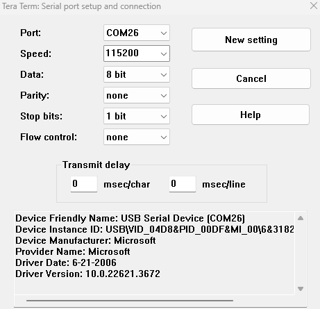
Open the Terminal application (e.g., Tera term) on the computer
-
Change the baud rate to 115200 from Setup>Serial menu
-
Press RESET button to run the application from the beginning
-
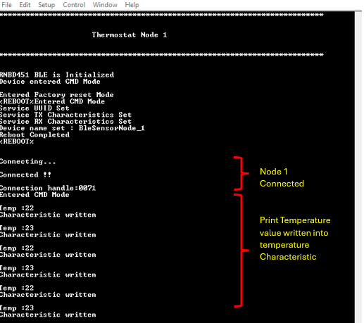
The below console output will be displayed. The last message on Tera Term will be
Connecting...where the node waits for a BLE connection
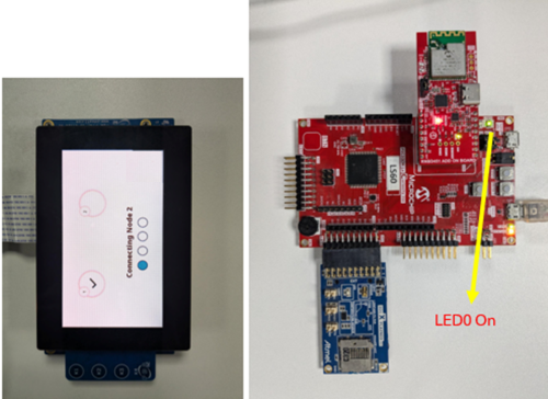
-
When the central node successfully connects, the LED0 (Green LED) turns on indicating successful connection
-
The measured temperature value prints on the console as below. Note that the temperature value prints only when the temperature changes
-
The BLE node receives the temperature threshold values set on the central node as below
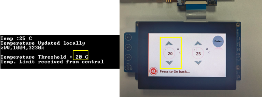
-
LED1 (Red LED) turns on whenever the current measured temperature is greater than the limit set on the GUI
Comments
- Getting Started with the PIC32CM LE00/LS00/LS60 Curiosity Pro Board (DS00004511)
- Reference Document: PIC32CM LS00/LS60 Security Reference Guide (DS00003992)
- This application demo builds
and works out of box by following the instructions above in Running the Demo
section. If the user needs to enhance/customize this application demo,
should use the MPLAB Harmony v3 Software framework. Refer to the following
links to setup and build the applications using MPLAB Harmony.
- How to Setup MPLAB Harmony v3 Software Development Framework (DS90003232)
- How to Build an Application by Adding a New PLIB, Driver, or Middleware to an Existing MPLAB Harmony v3 Project (DS90003253)
- Video - How to Set up the Tools Required to Get Started with MPLAB® Harmony v3 and MCC
- Create a new MPLAB Harmony v3 project using MCC
- Update and Configure an Existing MHC-based MPLAB Harmony v3 Project to MCC-based Project