
3.1.3 Smart Wireless Thermostat on PIC32CZ CA90 Curiosity Ultra Development Board
Description
This wireless thermostat application uses Bluetooth Low Energy 5.2 and Wi-Fi technology to collect real-time temperature data from two BLE sensor nodes. It allows users to easily set and control the temperature, creating a pleasant environment by adjusting the heating or cooling system to their desired level through an intuitive BLE central node acting as a wireless thermostat that connects to the end nodes over BLE and acts as the temperature control panel. The collected temperature is streamed through the Wi-Fi Gateway node to the AWS IoT cloud for monitoring. This solution includes four projects to demonstrate a Wireless Thermostat.
- Wireless Thermostat
Central Control Panel - (PIC32CZ_CA90 Central BLE Node
Application):
This project employs the RNBD451 BLE module to create multi-link BLE connections with two peripheral nodes. Once connected, the central node functions as a GATT client, periodically requesting real-time temperature data from the peripheral GATT servers(peripherals) and displaying it on a 4.3-inch maXTouch® graphics display. Users can set and send temperature threshold limits to the BLE peripheral nodes using the GUI. In addition, the central application transmits the gathered temperature data to the WFI32 IoT gateway through UART for real-time monitoring on the AWS cloud.
- Wireless Thermostat
Peripheral BLE Sensor Node 1 - (PIC32CM_LS60 BLE Peripheral
Node):
This application operates as a GATT server using the RNBD451 BLE module. It periodically collects temperature data from the IO/1 Xplained Pro board and updates the temperature characteristic value whenever the temperature changes. The node waits for the connection request from the central node. Once connected, it sends temperature data in response to read requests from the GATT client(central node) and can receive and implement threshold limit values from the central node. An onboard LED turns on whenever the temperature exceeds the designated limit.
- Wireless Thermostat
Peripheral BLE Sensor Node 2 - (WBZ451 BLE Peripheral
Node):
This application uses ADC to read the analog output from the onboard MCP9700A temperature sensor. Once connected to central node over BLE, it periodically sends the temperature characteristic value to the central node upon request. It can receive and set threshold limit values from the central node, with an onboard LED illuminating when the temperature surpasses the defined cutoff.
- Wireless Thermostat
Gateway - (WFI32 IoT Wi-Fi-Gateway):
This application acts as bridge between the central node and the AWS cloud. It periodically receives the BLE end nodes temperature data from the central over UART and publishes the same over MQTT to the AWS IoT cloud for constant monitoring.
Modules/Technology Used
Hardware Used
Software/Tools Used
The projects have been verified to work with the following versions of software tools:
- For Central PIC32CZ_CA90 GATT Client, refer to the Project Manifest
- For peripheral PIC32CM_LS60 GATT Server, refer to the Secure Project Manifest and Non-Secure Project Manifest
- For peripheral WBZ451 GATT Server, refer to the Project Manifest
- For Wi-Fi Gateway PIC32MZ_W1, refer to the Project Manifest
- MPLAB® X IDE v6.20
- MPLAB® XC32 C/C++ Compiler v4.45
- Any Serial Terminal application, such as Tera Term terminal
- Python v3.5 or higher
Due to Microchip regularly updates tools, occasionally issue(s) could be discovered while using the newer versions of the tools. If the project does not seem to work and version incompatibility is suspected. It is recommended to double-check and use the same versions that the project was tested with. To download original version of MPLAB Harmony v3 packages, refer to the document How to Use the MPLAB Harmony v3 Project Manifest Feature (DS90003305).
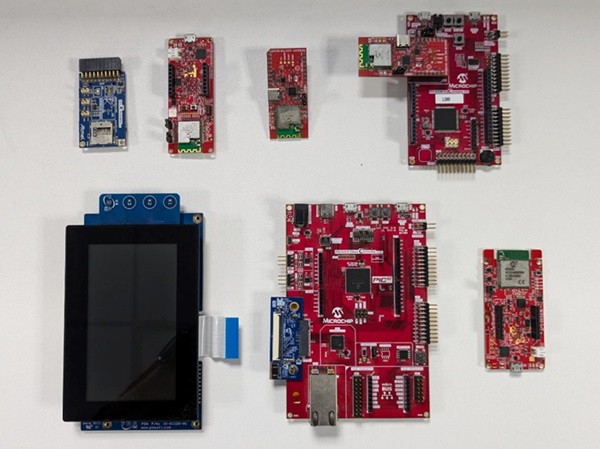
Hardware Setup
-
Connect the 565 LCD Adapter Graphics Card to the Graphics connector of the PIC32CZ CA90 Curiosity Ultra development board
-
Connect the 4.3” WQVGA maXTouch Display module to the 565 LCD Adapter Graphics Card of the PIC32CZ CA90 Curiosity Ultra development board
-
Ensure the jumper J2 of the RNBD451 Add On Board has the cap mounted between J(2-1) and J(2-2) to be powered by the mikroBUS header
-
Connect the jumper wire from PC08 on EXT1 for SERCOM UART TX to communicate with the Wi-Fi Gateway
-
Connect the PIC32CZ CA90 Curiosity Ultra development board to the host PC as a USB device through a Type-A male to Micro-B USB cable connected to Micro-B USB (Debug USB) port
-
Power the PIC32CZ CA90 Curiosity Ultra development board through the Barrel connector using the wall-mount 9V power supply provided in the kit, or Power supply with any Voltage (6.5 to 14V DC) and Current (>750 mA) range
-
Connect the RNBD Add-on board to the mikroBUS header on the PIC32CM LS60 Curiosity Pro evaluation kit
-
Ensure the jumper J2 of the RNBD451 Add On Board has the cap mounted between J(2-1) and J(2-2) to be powered by the mikroBUS header
-
Connect the I/O1 Xplained Pro Extension kit to the EXT2 in the PIC32CM LS60 Curiosity Pro evaluation kit
-
Connect the PIC32CM LS60 Curiosity Pro evaluation kit to the host PC as a USB device through a Type-A male to Micro-B USB cable connected to Micro-B USB (Debug USB) port
-
Connect the WBZ451 Curiosity board to the host PC as a USB device through a Type-A male to Micro-B USB cable connected to Micro-B Debug USB port (J7)
- Connect the WFI32 IoT
development board to the host PC as a USB device through a Type-A male to
Micro-B USB cable connected to PKOB4 Micro-B USB (Debug USB) (J200)
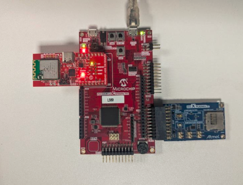
Figure 3-1. Demo Hardware Setup 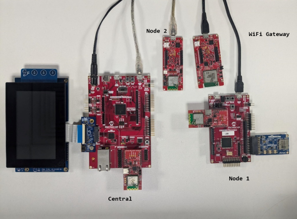
Prerequisites
- The WFI32E01PC module on the WFI32 IoT development board has an in-built Trust and Go (TNG) device. It is essential to upload the device certificate of the TNG device to the AWS IoT cloud for authenticated client TLS connection with the cloud platform.
- Follow the procedure mentioned in Generate Device Certificate for extracting the certificate from the device.
- Upon generation, the device certificate should be uploaded to the cloud. Refer to the Uploading Device Certificate to AWS IoT Cloud Service section for more details about the procedure.
- The
configuration.hfile ofwfi32_iot.Xproject should be modified for connecting successfully to the AWS cloud.- Ensure that the WIFI
SSID and WIFI Password is modified in the file by changing the
SYS_WIFI_STA_SSIDandSYS_WIFI_STA_PWDmacros with the Wi-Fi credentials. - Ensure that the aws
endpoint and aws thing name are properly set in the
SYS_MQTT_INDEX0_BROKER_NAMEandSYS_MQTT_INDEX0_CLIENT_IDmacros respectively. This depends on user-specific AWS account credentials. For more details, refer to the AWS Account Setup section.
- Ensure that the WIFI
SSID and WIFI Password is modified in the file by changing the
Programming Methods
- The device can be
programmed in two ways:
-
Refer to Method 1: Programming using the prebuilt hex file
-
Refer to Method 2: Programming by building the application project
-
- Perform Prerequisites mentioned above, if not done already
Method 1: Programming Prebuilt Hex File
- Open MPLAB X IDE
- Close all existing projects in IDE, if any project is opened
- Go to File>Import>Hex/ELF file
- In the Import Image File
window,
- Create Prebuilt
Project,
- Click the Browse button to select the prebuilt hex file
- Select Device as PIC32CZ8110CA90208
- Ensure the proper tool is selected under Hardware Tool and click the Next button
- Select Project Name
and Folder,
- Select appropriate project name and folder and click the Finish button
- Create Prebuilt
Project,
- In MPLAB X IDE, click the Make and Program Device button to program the device
- Follow the steps in Running the Demo under PIC32CZ CA90 Central section below
Method 2: Programming/Debugging the Application Project
- Open the project
ls60_cprogroup.Xin MPLAB X IDE frompic32cz_ca90_wireless_thermostat/firmware/pic32cm_ls60_cpro_wt_node1and set it as main project - Open both Secure and Nonsecure projects inside the project group and set the Nonsecure project as the main project
- Ensure
PIC32CM
                                LS60 Curiosity Pro
is selected as hardware tool to program/debug the application - Build the code and program the device by clicking on the Make and Program button in MPLAB X IDE tool bar
- Follow the steps in Running the Demo under PIC32CM LS60 Peripheral Node section below
- Open the project
wbz451_curiosity.Xin MPLAB X IDE frompic32cz_ca90_wireless_thermostat/firmware/wbz451_curiosity_wt_node2and set it as main project - Ensure
WBZ451
                                Curiosity board
is selected as hardware tool to program/debug the application - Build the code and program the device by clicking on the Make and Program button in MPLAB X IDE tool bar
- Follow the steps in Running the Demo under WBZ451 Peripheral Node section below
- Open the project
pic32cz_ca90_cult.Xin MPLAB X IDE frompic32cz_ca90_wireless_thermostat/firmware/pic32cz_ca90_cult_wt_centraland set it as main project - Ensure
PIC32CZ
                                CA90 Curiosity Ultra
is selected as hardware tool to program/debug the application - Build the code and program the device by clicking on the Make and Program button in MPLAB X IDE tool bar
- Follow the steps in Running the Demo under PIC32CZ CA90 Central Node section below
- Open the project
wfi32_iot.Xin MPLAB X IDE frompic32cz_ca90_wireless_thermostat/firmware/wfi32_iot_wt_gatewayand set it as main project - Ensure
WFI32 IoT
                                board
is selected as hardware tool to program/debug the application - Build the code and program the device by clicking on the Make and Program button in MPLAB X IDE tool bar
- Follow the steps in Running the Demo under WFI32 IoT Gateway section below
Running the Demo

PIC32CZCA90 BLE Central Node
- Power up the board. Ensure the 4.3" WQVGA maXTouch Display Module is connected to the 565 LCD Adapter Graphics Card and press RESET button of the PIC32CZ CA90 Curiosity Ultra development board.
Screen 1: Home Screen
- The home screen of the demo
gets displayed on the 4.3” WQVGA maXTouch Display Module.

- Ensure that the BLE
peripheral nodes,
NODE 1andNODE 2, are programmed with the respective application projects and both the nodes are ready to connect to the central node.Note: Before proceeding to the next step, ensure the console messages shown on the peripheral Node 1 and Node 2 are as Node 1 Ready Status and Node 2 Ready Status. - Press the START button
on the home screen.

Screen 2: Multi-Connect Screen
- The central node starts to
scan for the nearby BLE peripheral nodes.
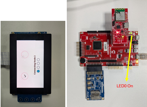
Scanningappears on the connect screen. Wait for a few seconds for the BLE scanning process to complete. - Once the scanning completes,
the central initiates connection with BLE Node 1.

- Upon successful connection with BLE node 1, a tick mark appears on the GUI
as below and LED0 is turned on.

- Similarly , the central node initiates another connection to BLE node 2.
- Upon successfully connecting
with the second node, a tick mark appears on the GUI, as below, and the next
screen appears that shows
Preparingappears. - LED0 and LED1 are turned on
with a successful multilink connection on the PIC32CZ CA90 Curiosity Ultra
development board as below.

Screen 3: Multi Node Sensor Monitoring
- This screen gets updated with
node 1 and node 2 temperature data fetched in periodic intervals from the
BLE peripheral devices.
 Note: The corresponding temperature can be viewed on the Tera term console of nodes 1 and 2.
 - Press Set Limit button
to assign threshold limit for the nodes to cutoff the heating or cooling
unit. Once Set Limit is pressed the next screen appears.Note: Wait for a couple of seconds if the next screen does not appear immediately.
Screen 4: Temperature Control
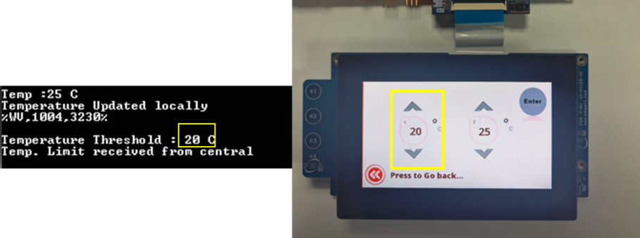
- Temperature limits can be set
for each of the nodes using the ᴧ (Increment) and v
(Decrement) buttons.

- To set threshold for node 1, adjust the temperature and press Enter.
- Similarly, to set threshold
for node 2, adjust the temperature for node 2 and press Enter.Note: Take into account that the limits for each node should be set individually. The nodes do not get updated simultaneously. To set threshold for both the nodes, change the limit in one node, press enter and then do the same for the other node.
- Press Press to Go back to go to screen 3.
PIC32CM LS60 BLE Peripheral Node
- Power up the board
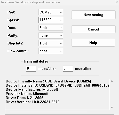
- Open the Terminal application (e.g., Tera term) on the computer
- Change the baud rate to
115200
- Press RESET button of the PIC32CM LS60 Curiosity Pro evaluation kit to run the application from the beginning
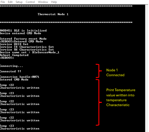
- The below console output will
be displayed. The last message on Tera Term will be
Connectingwhere the node waits for a BLE connection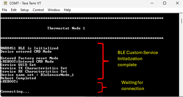
- When the central node
successfully connects (after pressing start on the central node GUI), the
LED0 (Green LED) turns on indicating successful connection
- The measured temperature
value prints on the console as below
- The BLE node receives the
temperature threshold values set on the central node as below
- LED1 (Red LED) on PIC32CM
LS60 Curiosity Pro evaluation kit turns on whenever the current temperature
is greater than the set limit
WBZ451 BLE Peripheral Node
- Power up the board
- Open the Terminal application (e.g., Tera term) on the computer
- Change the baud rate to 115200
- Press RESET button to start over the application
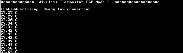
- The device starts BLE
advertisement and displays the current temperature in periodic intervals
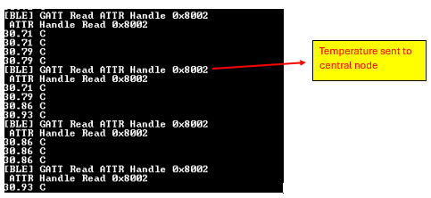
- Once the connection with the
central node is successful, it sends the current temperature value to the
central node

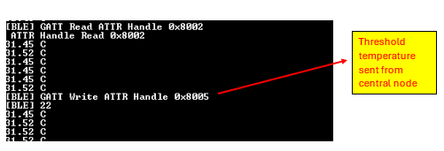
- The BLE node receives the temperature threshold values set on the central node
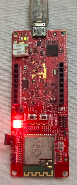
- The RGB LED (D6) of the
WBZ451 Curiosity development board glows in Red when the current temperature
exceeds the threshold set. In the above image the current temperature (31°C)
is greater than the received threshold (22°C). The LED turns on in this
scenario.
WFI32 IoT Wi-Fi Gateway Node
- Power up the board.
- Open the Terminal application (e.g., Tera term) on the computer.
- Change the baud rate to
115200 from Setup>Serial menu.
- Press RESET button to run the application from the beginning.
- The console displays
TCP/IP stack initialization messages and the Gateway IP address gets
assigned and displayed on successful connection with Wi-Fi AP. Wait for
some time for the MQTT connection establishment as it may take some
time.

- Once the MQTT connection is established the device is ready to update the temperature received from the central node in AWS cloud periodically.
- The device starts to
publish the messages when the central node updates the temperature.

- To view the messages
published, log in to the AWS account and navigate to the AWS IoT Core
service>MQTT Test client, and subscribe to
/pubTopic/. In addition, the following messages will be displayed.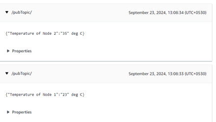
Comments
- Getting Started Extended Application on PIC32CZ CA90 Curiosity Ultra Development Board
- Creating the First Application on PIC32CZ CAx Microcontrollers Using MPLAB® Harmony v3 with MPLAB® Code Configurator (MCC) (DS90003348)
- Getting Started with the PIC32CM LE00/LS00/LS60 Curiosity Pro Board (DS00004511)
- PIC32CM LS00/LS60 Security Reference Guide (DS00003992)
- PIC32CXBZ2 Application Developer's Guide
- MPLAB Harmony Wireless BLE User Guide
- PIC32CX-BZ2 Programming Specification (DS70005461)
- This application demo
builds and works out of box by following the instructions above in
Running the Demo section. If the user needs to enhance/customize this
application demo, should use the MPLAB Harmony v3 Software framework.
Refer to the following links to setup and build the applications using
MPLAB Harmony.
- How to Setup MPLAB Harmony v3 Software Development Framework (DS90003232)
- How to Build an Application by Adding a New PLIB, Driver, or Middleware to an Existing MPLAB Harmony v3 Project (DS90003253)
- Video - How to Set up the Tools Required to Get Started with MPLAB® Harmony v3 and MCC
- Create a new MPLAB Harmony v3 project using MCC
- Update and Configure an Existing MHC-based MPLAB Harmony v3 Project to MCC-based Project