
50.4.15 SPI Mode Requirements
| Standard Operating Conditions (unless otherwise stated) | |||||||
|---|---|---|---|---|---|---|---|
| Param No. | Sym. | Characteristic | Min. | Typ. † | Max. | Units | Conditions |
| TSCK | SCK Cycle Time (2x Prescaled) | 61 | — | — | ns | Transmit Only mode | |
| — | 16(1) | — | MHz | ||||
| 95 | — | — | ns | Full Duplex mode | |||
| — | 10(1) | — | MHz | ||||
| SP70* |
TSSL2SCH, TSSL2SCL | SDO to SCK↓ or SCK↑ input | TSCK | — | — | ns | FST = 0 |
| 0 | — | — | ns | FST = 1 | |||
| SP71* | TSCH | SCK output high time | 0.5 TSCK - 12 | — | 0.5 TSCK + 12 | ns | |
| SP72* | TSCL | SCK output low time | 0.5 TSCK - 12 | — | 0.5 TSCK + 12 | ns | |
| SP73* |
TDIV2SCH, TDIV2SCL | Setup time of SDI data input to SCK edge | 85 | — | — | ns | |
| SP74* |
TSCH2DIL, TSCL2DIL | Hold time of SDI data input to SCK edge | 0 | — | — | ns | |
| Hold time of SDI data input to final SCK | 0.5 TSCK | ns | CKE = 0,SMP = | ||||
| SP75* | TDOR | SDO data output rise time | — | 10 | 25 | ns | CL = 50 pF |
| SP76* | TDOF | SDO data output fall time | — | 10 | 25 | ns | CL = 50 pF |
| SP78* | TSCR | SCK output rise time | — | 10 | 25 | ns | CL = 50 pF |
| SP79* | TSCF | SCK output fall time | — | 10 | 25 | ns | CL = 50 pF |
| SP80* |
TSCH2DOV, TSCL2DOV | SDO data output valid after SCK edge | -15 | — | 15 | ns | CL = 50 pF |
| SP81* |
TDOV2SCH, TDOV2SCL | SDO data output valid to first SCK edge | TSCK - 10 | — | — | ns |
CL = 50 pF CKE = |
| SP82* | TSSL2DOV | SDO data output valid after SS↓ edge | — | — | 50 | ns | CL = 20 pF |
| SP83* |
TSCH2SSH, TSCL2SSH | SS ↑ after last SCK edge | TSCK - 10 | — | — | ns | |
| SP84* |
TSSH2SSL | SS ↑ to SS↓ edge | TSCK - 10 | — | — | ns | |
|
* These parameters are characterized but not tested. † Data in “Typ” column is at 3.0V, 25°C unless otherwise stated. These parameters are for design guidance only and are not tested. Note:
| |||||||
| Standard Operating Conditions (unless otherwise stated) | |||||||
|---|---|---|---|---|---|---|---|
| Param No. | Sym. | Characteristic | Min. | Typ. † | Max. | Units | Conditions |
| TSCK | SCK Total Cycle Time | 47 | — | — | ns | Receive Only mode | |
| — | 20(1) | — | MHz | ||||
| 95 | — | — | ns | Full-Duplex mode | |||
| — | 10(1) | — | MHz | ||||
| SP70* |
TSSL2SCH, TSSL2SCL | SS↓ to SCK↓ or SCK↑ input | 0 | — | — | ns | CKE = 0 |
| 25 | — | — | ns | CKE = 1 | |||
| SP71* | TSCH | SCK input high time | 20 | — | — | ns | |
| SP72* | TSCL | SCK input low time | 20 | — | — | ns | |
| SP73* |
TDIV2SCH, TDIV2SCL | Setup time of SDI data input to SCK edge | 10 | — | — | ns | |
| SP74* |
TSCH2DIL, TSCL2DIL | Hold time of SDI data input to SCK edge | 0 | — | — | ns | |
| SP75* | TDOR | SDO data output rise time | — | 10 | 25 | ns | CL = 50 pF |
| SP76* | TDOF | SDO data output fall time | — | 10 | 25 | ns | CL = 50 pF |
| SP77* | TSSH2DOZ | SS↑ to SDO output high-impedance | — | — | 85 | ns | |
| SP80* |
TSCH2DOV, TSCL2DOV | SDO data output valid after SCK edge | — | — | 85 | ns | |
| SP82* | TSSL2DOV | SDO data output valid after SS↓ edge | — | — | 85 | ns | |
| SP83* |
TSCH2SSH, TSCL2SSH | SS ↑ after SCK edge | 20 | — | — | ns | |
| SP84* |
TSSH2SSL | SS ↑ to SS↓ edge | 47 | — | — | ns | |
|
* These parameters are characterized but not tested. † Data in “Typ” column is at 3.0V, 25°C unless otherwise stated. These parameters are for design guidance only and are not tested. Note:
| |||||||
0, SMP = 0)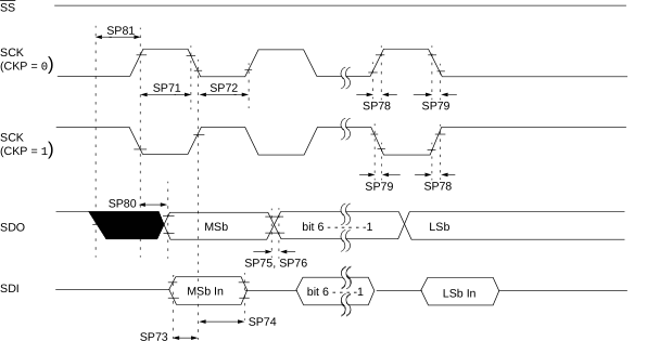
Note: Refer to the Load
Conditions figure for more details.
1, SMP = 1)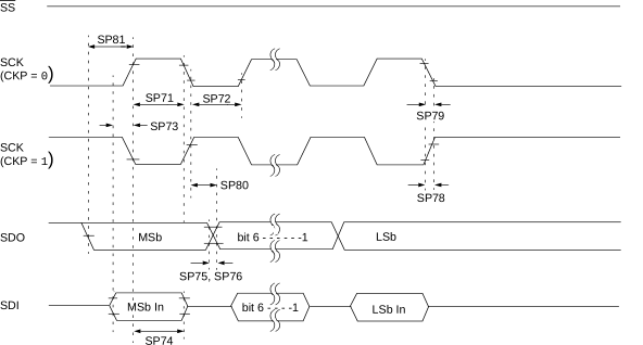
Note: Refer to the Load
Conditions figure for more details.
0)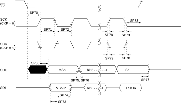
Note: Refer to the Load
Conditions figure for more details.
1)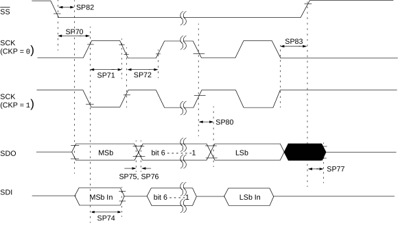
Note: Refer to the Load
Conditions figure for more details.