
3.1.6 Simulate Design
After creating the new CUPL Simulation input file (AND_2.si), the next step is to run a functional simulation of the CUPL design in WinCUPL II.
At the end of the simulation process, a message prompt indicating that the design has been successfully simulated will appear. This message is also shown in the Message pane of the WinCUPL II window, as well as in the LOG file.
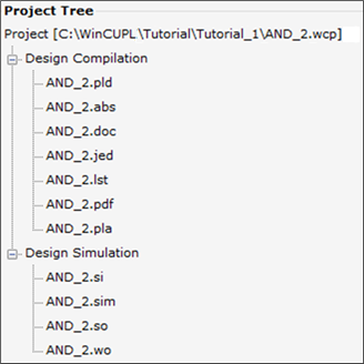
The simulation results are contained in the Simulation Output file (AND_2.so). You can double click this file in the Project Tree to open it in the built-in text editor and view the simulation results.
If there are any simulation errors, they will be shown in this file.
After successfully compiling and simulating the AND_2 design in WinCUPL II, select File ➔ Save Project or click the Save Project shortcut button to save the project.