11.2.5.2.2 Step 2. Connect MPLAB ICE 4 to a Target
Connect the MPLAB ICE 4 In-Circuit Emulator (DV244140) to your target hardware using one of the following methods:
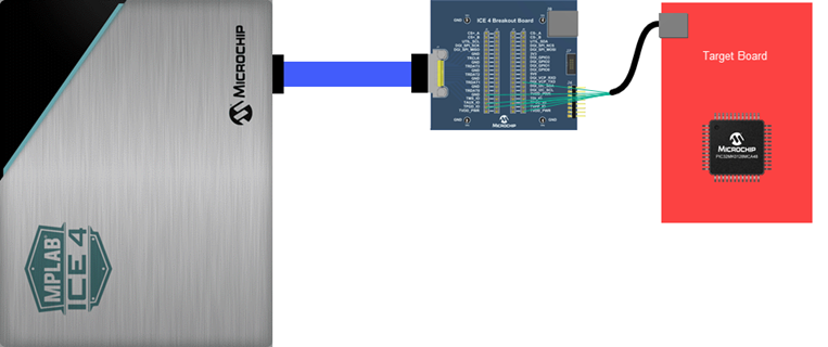
- Connect MPLAB ICE 4 40-pin ribbon cable to the MPLAB ICE 4 Breakout Board (AC244141). Then connect the Breakout Board pins to the corresponding target ICSP modular connector pins as specified in the table below.
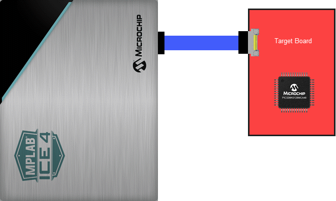
- Connect MPLAB ICE 4 40-pin ribbon cable directly to a 40-pin connector on the target. Ensure that the 40-pin connector pins map to the target device ICSP pins as specified in the table below.
The ICSP pins are required to debug and program the device, and the DGI_VCP_TXD and DGI_VCP_RXD pins are required to read the serial output. The DGI_VCP_TXD and DGI_VCP_RXD need to be connected to the pins which you have configured for your serial driver to use.
| ICE 4 Function Names1,2 | ICE 4 Breakout Board Pins1 | ICE 4 Connector Pins at Target2 | Target ICSP Names3 | Target ICSP Pins3 |
|---|---|---|---|---|
| TVPP_IO | J4/5 19 | 37 | MCLR/VPP | 1 |
| TVDD_PWR | J2/3/4/5 20 | 39,40 | VDD | 2 |
| GND | J2/3 6,8,10,12,14,16 | 12,16,20,24,28,32 | VSS | 3 |
| TPGD_IO | J2/3 19 | 38 | TGO/PGD | 4 |
| TPGC_IO | J4/5 18 | 35 | TCK/PGC | 5 |
| TAUX_IO | J2/3 18 | 36 | TAUX | 6 |
| DGI_VCP_TXD | J4/5 13 | 25 | TMS4 | 7 - TX pin used by configured serial driver |
| DGI_VCP_RXD | J4/5 12 | 23 | TDI4 | 8 - RX pin used by configured serial driver |
| ||||