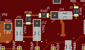
There are three jumpers that need to be modified to change the board configuration from
the default mode of using 3.3V Flash chips to using 1.8V chips. Jumpers J10, J12 and J14
can be changed by moving the jumper cap. No trace-link jumper needs to be cut for the R3
board revision.Figure 4-9. R3 Revision - Jumpers for
Settings 1.8V SPI Operation
Note: Pin 1 is indicated by the dot near the
connector
The diagram above shows the 3.3V default settings. To power VTR1 with 1.8V, move jumper
J10 from the (1-2) position to the (2-3) position. Note that this power setting must
match the BMC Host power setting. To Power VTR2 with 1.8V, move jumper J12 and Jumper
J14 to the (2-3) position. Both J12 and J14 must be set to the same supply voltage
level.
The online versions of the documents are provided as a courtesy. Verify all content and data in the device’s PDF documentation found on the device product page.