
4.4.1 MCC SMPS Library Configuration for VMC Closed Loop
The following instructions show how to setup the peripherals of the CIP Hybrid Power Starter Kit to be able to operate in VMC test mode.
- Open MPLAB X. Connect the CIP Hybrid Power Starter Kit to the computer through an on-board debugger USB port using a conventional micro-USB cable. MPLAB X will detect the CIP Hybrid Power Starter Kit and an Xplained Window appears that provides relevant information about the board.
- Create new Standalone Project in MPLAB X. Select the PIC16F1779 device. Select the CIP Hybrid Starter Kit as programming tool. Name this project “VMC”.
- Open MCC. Save the MCC configuration
as
VMC.mc3. - In the Project Resources area, change the internal oscillator clock to 8 MHz from the System Module. On the Pin Manager, change the package to QFN44.
- Go to the Device Resources area, click SMPS Power Controllers and expand Power Supply Topologies, double click on SyncBuck. This action will move the SyncBuck to the Project Resources area.
- In the Project Resources area, click on SyncBuck. On the Configuration tab, under Hardware Settings, select VMC as control mode. Change the switching frequency to 500 kHz, the duty cycle to 90%, reference voltage to 2.5V, leading edge blanking to 250 ns, rising edge dead time to 50 ns and falling edge dead time to 40 ns. Add sawtooth ramp of 2.5V/us. Choose PWM Controller Block 2.
- Click the Upload All button.
This action will load all the peripherals of the PWM Controller Block 2 on the
Project Resources area.
Figure 4-32. Hardware Settings for VMC Synchronous Buck Converter 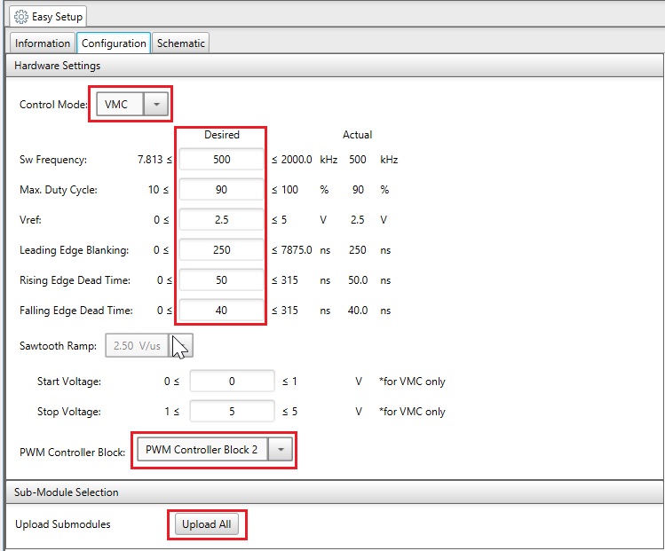
- When all the peripherals are loaded, the sawtooth ramp slope will automatically be updated to 2.5 V/us. This is computed with start voltage of 0V, a stop voltage of 5V, and the switching frequency of 500 kHz using the formula Ramp = (stop voltage – start voltage) / (2*switching frequency).
- Go to the Pin Manager: Grid View.
Assign RB1 as output pin for signal EA_O, RB2 as input pin for signal FB, RD5 as
output pin for signal OUT_H and RD4 as output pin for signal OUT_L.
Figure 4-33. Pin Assignments for Sync Buck VMC 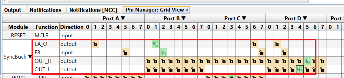
- Soft start is enabled by default on
the VMC Control Mode section.
Figure 4-34. Pin Assignments for Sync Buck VMC 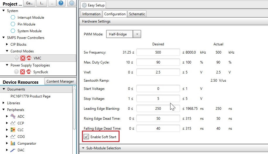
- Enabling the soft start disables the COG, PWM and OPA peripherals at power on.
- Click the Generate button to
generate the code. On the
main.c, add the following line of code,VMC_SoftStart();.Figure 4-35. Inserting ‘ VMC_SoftStart()’ Function Insidemain.c - Program the PIC16F1779 device on the CIP Hybrid Power Starter Kit by clicking the ”Make and Program Device Main Project” icon.
- Alternatively, the user can also
download the PCMC firmware to the CIP Hybrid Power Starter Kit by dragging the
generated
.hexfile of the project to the CURIOSITY drive. The.hexfile is located on the --dist\default\production folder. - The board is now configured in VMC operation.