
1.1.11.1.3 Configuring The Library
The AT25 driver library should be configured through the MHC. The following figures show the MHC configuration window for the AT25 driver and brief description.
AT25 Driver with SPI peripheral connected
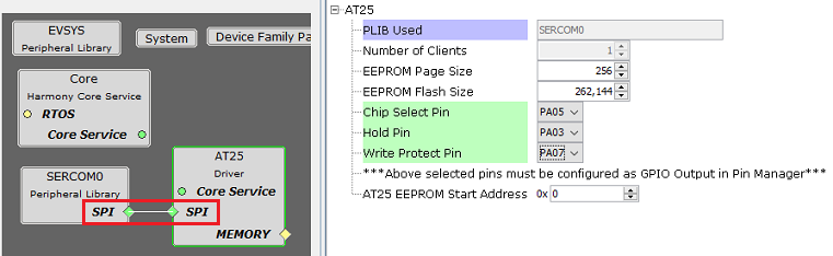
Configuration Options
PLIB Used:
- Specifies the Peripheral library connected
Number Of Clients:
Indicates maximum number of clients
Always set to one as it supports only a single client
EEPROM Page Size:
- Size of one page of EEPROM memory (in bytes)
EEPROM Flash Size:
- Total Size of the EEPROM memory (in bytes)
- Depending on the specified EEPROM Flash Size, the driver will generate the appropriate number of address bits (8-bit, 16-bit or 24-bit), thereby allowing it to communicate with EEPROM of different sizes in the AT25 family
Chip Select Pin:
FLASH chip select pin (active low)
This pin must be configured as GPIO output in "Pin Settings" configuration
Hold Pin:
- EEPROM hold pin (active low)
- This pin must be configured as GPIO output in "Pin Settings" configuration
Write Protect Pin:
- EEPROM write protect pin (active low).
- This pin must be configured as GPIO output in "Pin Settings" configuration.
- The AT25 driver keeps the Write Protect pin in logic high state, which means writes are always allowed
AT25 EEPROM Start Address:
Specifies the EEPROM memory start address to be used for Transfer operations
The start address will be populated in the device geometry table DRV_AT25_GEOMETRY