
4.2 TOSC1,TOSC2 Pin Configuration
Except multiplexing internal inverting amplifier oscillator XTAL1,XTAL2 pins, the PB6,PB7 can also be used as Timer2/Counter2 oscillator TOSC1,TOSC2 pins. The Timer/Counter Oscillator can only be used when the Calibrated Internal RC Oscillator is selected as system clock source. So for the TOSC multiplexing function selection, it needs to program the CKSEL fuse to “calibrated internal RC oscillator” and AS2 bit in ASSR register for enabling asynchronous clocking of Timer2/Counter2.
The Timer2/Counter2 clock can also be input externally. Once the “EXCLK” bit in the ASSR register is set, the external clock can be input from the TOSC1 pin.
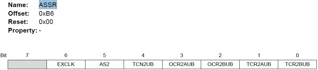
Bit 6 – EXCLK: Enable External Clock Input
When EXCLK is written to one, and asynchronous clock is selected, the external clock input buffer is enabled and an external clock can be input on Timer Oscillator 1 (TOSC1) pin instead of a 32kHz crystal.
Bit 5 – AS2: Asynchronous Timer/Counter2
When AS2 is written to zero, Timer/Counter2 is clocked from the I/O clock, clkI/O. When AS2 is written to one, Timer/Counter2 is clocked from a crystal Oscillator connected to the Timer Oscillator pin.