- The Curiosity High Pin Count (HPC)
Development Board (DM164136) is used as the test platform. Switch S1 and S2 are used
to select the ADC2 mode, and LEDs D2, D3, D4, D5 are used to display
which mode is active.
- A signal from the Signal & Noise
Generator board is connected to an analog input
(RA1) of the HPC.
- The Power Debugger includes a CDC
virtual COM port interface, which is used to transmit ADC2’s conversion
results to a PC over the EUSART to the Data Visualizer. The EUSART TX (pin RC6) of
the HPC is connected to CDC 'TX ←' pin of Power Debugger.
- HPC uses USB power supply, configured
to 3.3V VCC by a jumper.
HW Setup: Curiosity HPC with Power Debugger and Signal & Noise
Generator
Board
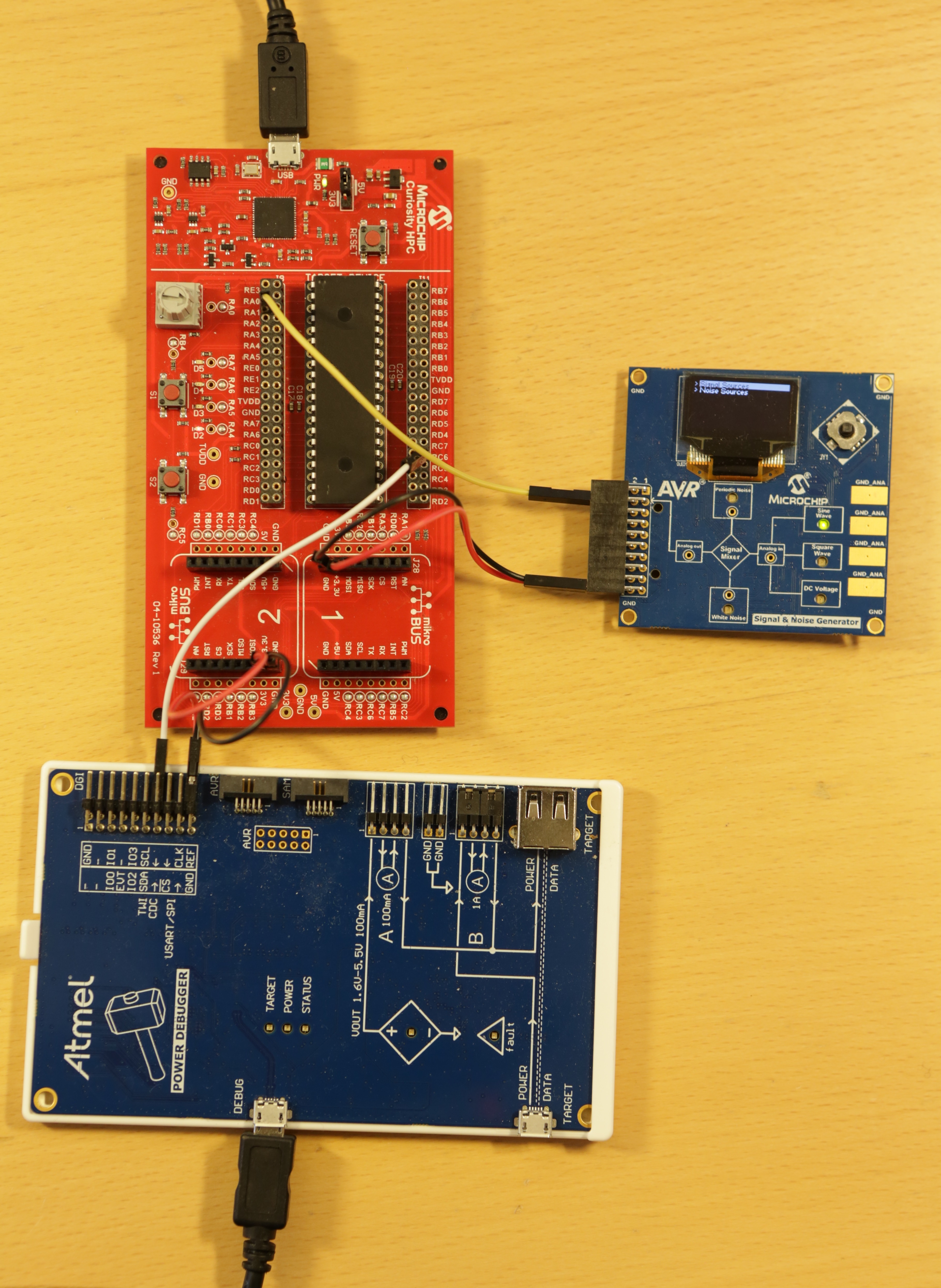
Table 4-1. HW Connection HPC- Signal & Noise
Generator| HPC | Signal & Noise
Generator |
|---|
| Pin | Pin Number | Name |
|---|
| RA1 | 3 | ADC(+) |
| GND | 19 | GND |
| 3V3 | 20 | VCC |
Table 4-2. HW Connection HPC- Power
Debugger| HPC | Power Debugger
(DGI port) |
|---|
| Pin | Pin Number | Name |
|---|
| RC6 | 14 | TX ← |
| GND | 19 | GND |
| 3V3 | 20 | VCC |
