
7 Quadrature Clock Generator
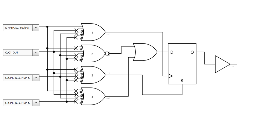
The CLC module can be used to create a quadrature clock generator which consists of two output clocks 90° out of phase of one another. A quadrature clock generator can be useful in many motor control and signal processing applications. For this application, two CLC modules in D Flip-Flop mode are used to create the circuit illustrated in Figure 7-1. The output signals of this circuit are half the frequency of the input signal. Figure 7-2 and Figure 7-3 show the configuration settings of each CLC module used in MCC. Quadrature Clock Generator Initialization Code shows the configuration code used to setup the modules for this application.
Two CLCs in D Flip-Flop mode are used to create the following circuit. The output signals are half the frequency of the input signal.
Quadrature Clock Generator Initialization Code
/*This code block configures the CLCs
for Quadrature Clock Generator.
*/
void CLC1_Initialize(void) {
CLCSELECT = 0x00; // SLCT 0
CLCnPOL = 0x02; // Gate and CLCnOUT Output polarity Selection
CLCnSEL0 = 0x0B; // D1S MFINTOSC_500khz
CLCnSEL1 = 0x33; // D2S CLC1_OUT
CLCnSEL2 = 0x00; // D3S CLCIN0 (CLCIN0PPS)
CLCnSEL3 = 0x00; // D4S CLCIN0 (CLCIN0PPS)
CLCnGLS0 = 0x02; // CLCn Gate 1 Logic Selection
CLCnGLS1 = 0x08; // CLCn Gate 2 Logic Selection
CLCnGLS2 = 0x00; // CLCn Gate 3 Logic Selection
CLCnGLS3 = 0x00; // CLCn Gate 4 Logic Selection
CLCDATA = 0x00; // CLC1OUT 0
CLCnCON = 0x85; // EN enabled; INTN disabled; INTP disabled; MODE 2-input D flip-flop with R
}
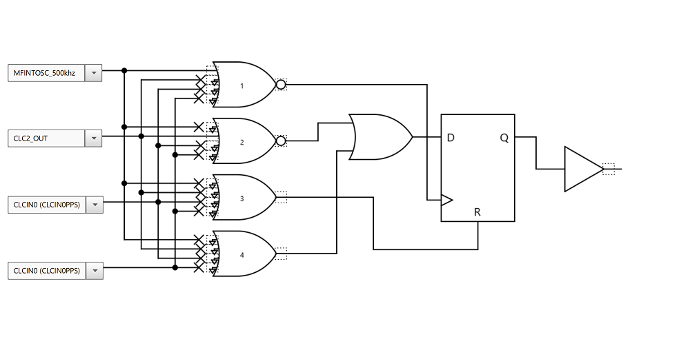
void CLC2_Initialize(void) {
CLCSELECT = 0x01; // SLCT 1
CLCnPOL = 0x03; // Gate and CLCnOUT Output polarity Selection
CLCnSEL0 = 0x0B; // D1S MFINTOSC_500khz
CLCnSEL1 = 0x34; // D2S CLC2_OUT
CLCnSEL2 = 0x00; // D3S CLCIN0 (CLCIN0PPS)
CLCnSEL3 = 0x00; // D4S CLCIN0 (CLCIN0PPS)
CLCnGLS0 = 0x02; // CLCn Gate 1 Logic Selection
CLCnGLS1 = 0x08 // CLCn Gate 1 Logic Selection
CLCnGLS2 = 0x00 // CLCn Gate 1 Logic Selection
CLCnGLS3 = 0x00; // CLCn Gate 1 Logic Selection
CLCDATA = 0x00; // CLC2OUT 0
CLCnCON = 0x85; // EN enabled; INTN disabled; INTP disabled; MODE 2-input D flip-flop with R
}