9 Developing a GUI Application with MGS
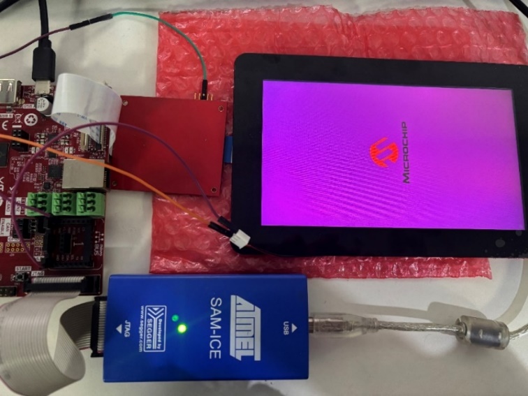
This section explains how to develop a simple application using the Microchip Graphics Suite (MGS). This application will demonstrate the functionality of the Raspberry Pi Touch Display 2 when used with the SAMA7D65-Curiosity board and a custom driver. The application will feature a 720x1280 User Interface (UI) with buttons and sliders, rendered via the ILI9881C controller.
Refer to the Microchip Graphics Suite (MGS) Harmony Composer user guide (see References).
To create and run a Legato-based GUI application with a purple background panel (#6B0080FF), follow these steps:
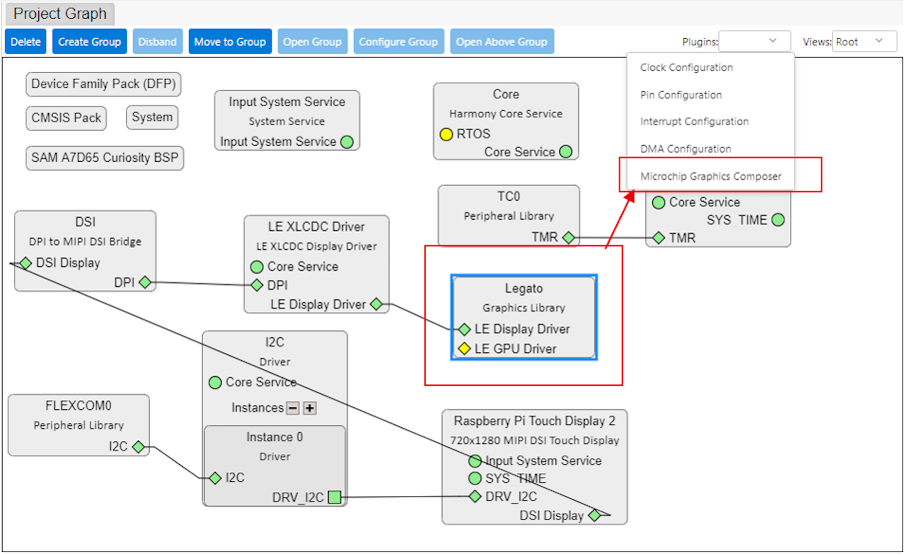
- Open Microchip Graphics Composer:
- In the Project Graph window, click on the Microchip Graphics Composer button. The Microchip Graphics Composer design tool opens.
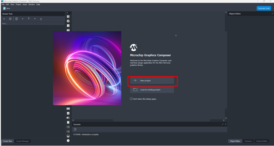
- Click on the New Project button
to launch the New Project wizard:
- Create the project:
- For a blank project, choose the
Clean Design template:
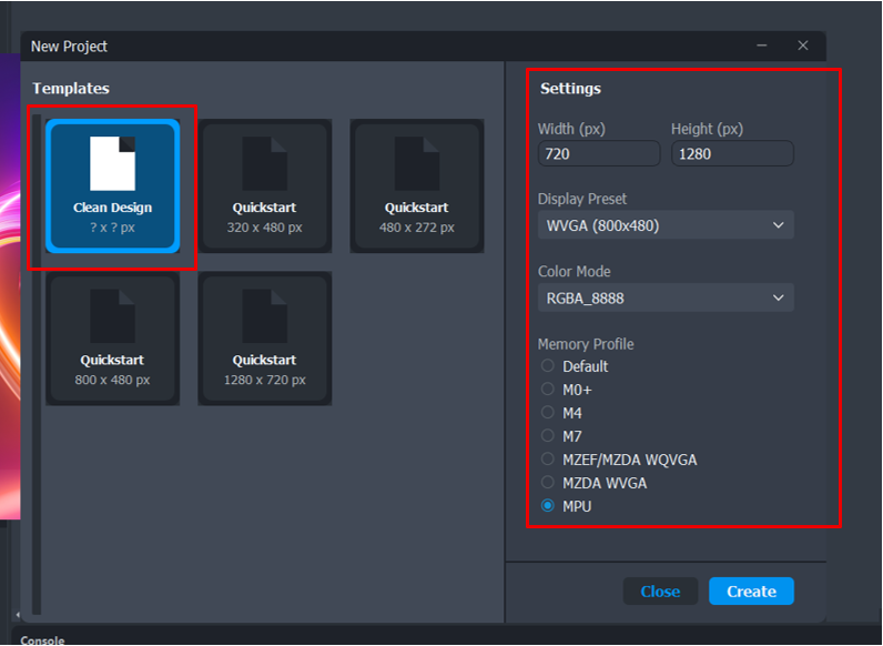
- In the Settings section, choose the display resolution either by selecting it in the Display Preset drop-down list or by manually entering the required width and height. In Color Mode, your choice must match the setting in the LCD driver project graph. Choose the Memory Profile setting based on your target.
- For a blank project, choose the
Clean Design template:
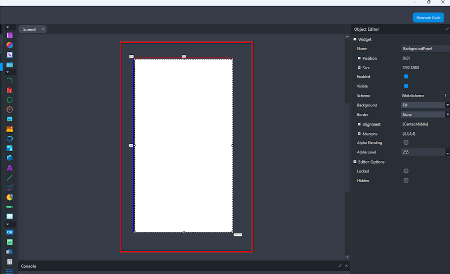
- Design with MGS Harmony Composer:
- In Design Canvas, select the background panel.
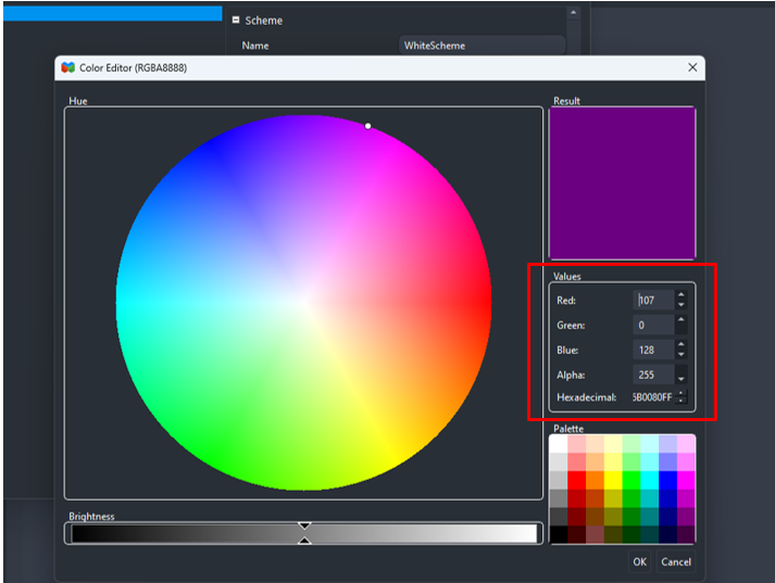
- In the object editor, locate the Background Scheme or Color setting. In the color table, click Base.
- Set the background color to Hex:
(Purple).
- Add an image:
- Go to the Assets tab.
- Click Add Image Asset, then browse and select the desired image file.
- Once the image file is imported, drag the image widget from the widget toolbox to the canvas.
- In the image widget Properties, set the image source to the newly added asset.
- Save the design file:
- Once the design is complete, click on the Save Design button (or, in the main menu, click on File > Save or Save As).
- When prompted to save the design, go to the MCC project configuration folder and provide the file name as <config_name>_design.zip. This ensures that when Microchip Graphics Composer is launched from the MCC plugin, the design will open automatically.
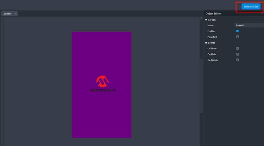
- Generate code from MGS:
- In MSG, click the Generate button.
- The console
displays a log message indicating that the output has been successfully
generated.
- Generate code from the MCC project
graph:
Once the MCC project graph and the graphics design using MGS Harmony Composer are completed, click the Generate button from the Resource Management [MCC] panel to generate the project code.
- Build and run the application:
- In MPLAB X, clean and build the project.
- Program the target board (using the SAM-ICE debugger, for example).
- Upon successful upload, the display should show your custom image with a purple background.