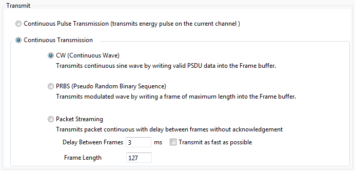
3.6.4.1 Continuous Transmission Tests
When the continuous transmission is enabled, by default, the firmware will set up Register 0x36 (TST_CTRL_DIGI) to enable the mode.
The continuous transmission can be done in two modes as described below.

-
Continuous Pulse Transmission:
The Continuous Pulse mode can be selected by selecting the 'Continuous Pulse Transmission' radio button.
To start the transmission the start button is clicked. Once the Continuous Pulse transmission is initiated, the transceiver transmits energy pulses on the current channel page until transmission stopped. The transmission is notified as 'transmitting' label.
-
Continuous Transmission:
The Continuous Wave mode can be selected by selecting the 'Continuous Wave Transmission' radio button.
Continuous Transmission can transmit in two modes:
-
CW (Continuous Wave).
In CW mode, the data rate is changed to a higher data rate (RG_TRX_CTRL_2) and then one pulse is transmitted (5ms of sine wave and 45ms idle period). To measure CW signals it is necessary to write valid data into the Frame Buffer.
-
In CW mode two different signal frequencies per channel can be transmitted:
-
f1 = fCH + 0.5MHz
-
f2 = fCH - 0.5MHz
-
Here fCH is the channel center frequency programmed by register 0x08 (PHY_CC_CCA)
-
Note, in CW mode it is not possible to transmit an RF signal directly on the channel center frequency
-
-
-
-
PRBS (Pseudo Random Binary Sequence).
In PRBS mode, one random number is generated and filled in the transceiver buffer and is transmitted continuously as frames.
-
Back-to-back Packet Transmission.
In this mode, a packet is repeatedly transmitted (back-to-back) without gaps in between the transmissions (gap as less as possible).
To start the transmission the start button is clicked. Once the Continuous wave transmission is initiated, the radio transceiver transmits continuously as previously transferred frame (PRBS mode) or a continuous wave signal (CW mode) on the current channel page until the Transmission Stopped.
To stop transmission click 'Stop' Icon.
Note:-
The Timeout option can be used to stop the continuous test automatically after the specified amount of time
-
In paired mode, when Continuous Transmission test is performed on Remote node, the only way to stop the test is to use the Timeout option. Otherwise, the connected kits needs to be disconnected, power cycled, and connected again.
-
All the options in Continuous Transmission tab will be available for the Host node. The Remote node will have lesser options.
-
Before enabling Continuous Transmission Test Mode all register configurations shall be done as follows:
-
TX channel setting (optional).
-
TX output power setting (optional).
-
Mode selection (PRBS/CW).
-
A register access to register 0x36 and 0x1C enables the Continuous Transmission Test Mode. (For example AT86RF231.)
-
The transmission is started by enabling the PLL (TRX_CMD = PLL_ON) and writing the TX_START command to register 0x02.
-
Even for CW signal transmission it is required to write valid PSDU data to the Frame Buffer.
-
For PRBS mode it is recommended to write a frame of maximum length (i.e., 127).
For more Information on continuous transmission, refer to the datasheet of the evaluation kit. Supported kits
-
-
