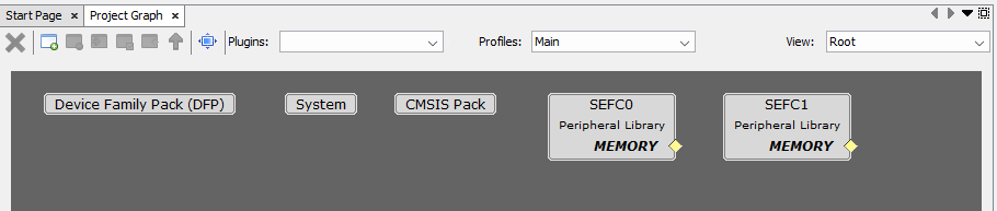
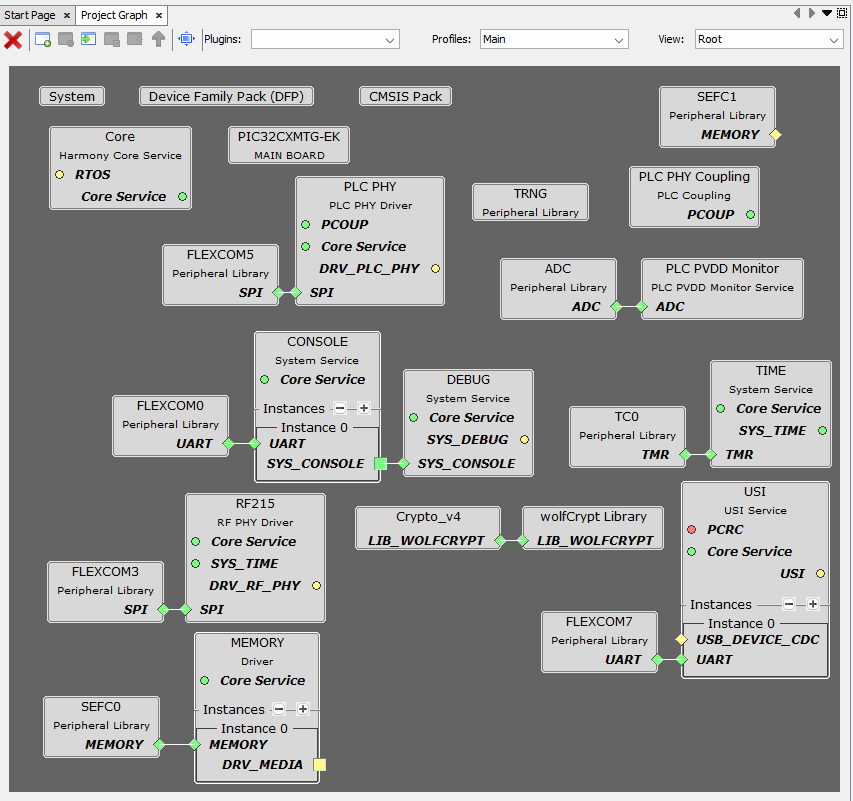
Go to MCC Project Graph window, as opened in previous step.Figure 2-6. MCC Project Graph
Add Board Component.
On Device Resources, navigate to
System Hardware Definitions (SHD)>Main Boards and click the + sign next to
PIC32CXMTG -EKFigure 2-7. Add Board Component
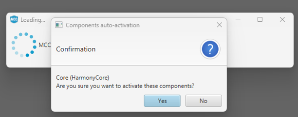
This triggers the Core Component Auto
ActivationFigure 2-8. Add Core Component
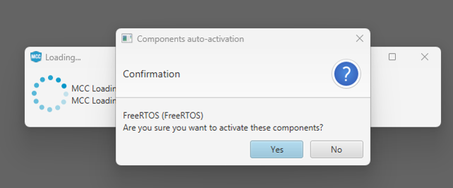
Click No when prompted for
adding FreeRTOS component. This example is a Baremetal project.Figure 2-9. Do Not Add FreeRTOS
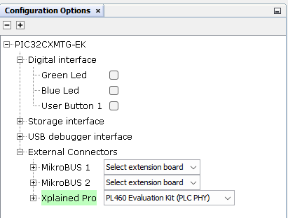
Connect PL460 Evaluation Kit.
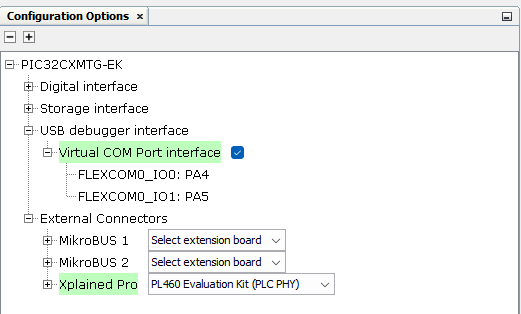
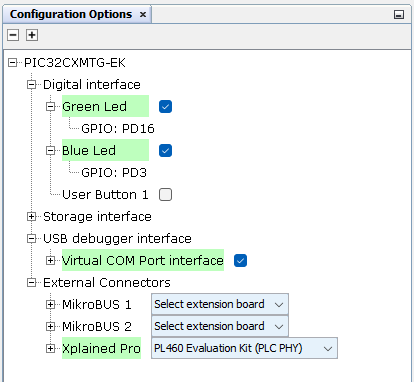
Click the PIC32CXMTG-EK component, on
Configuration Options set the Xplained Pro on External Connectors to PL460
Evaluation Kit (PLC PHY)Figure 2-10. Configure Xplained Pro
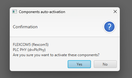
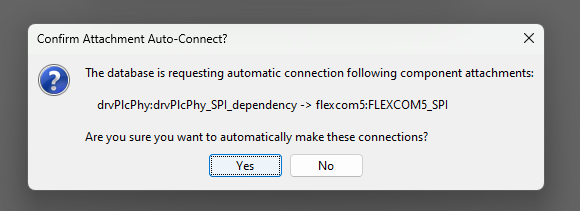
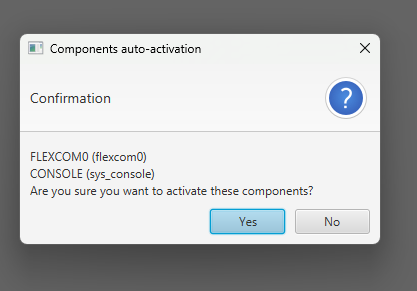
This triggers the PLC PHY Driver and
FLEXCOM5 Auto Activation and Auto ConnectionFigure 2-11. Add PLC PHY ComponentFigure 2-12. Connect PLC PHY and FLEXCOM5
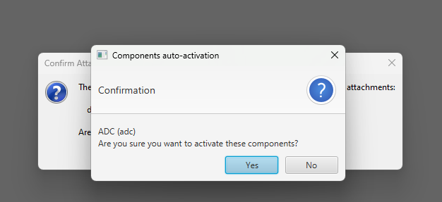
This triggers the ADC Auto
ActivationFigure 2-13. Add ADC Component
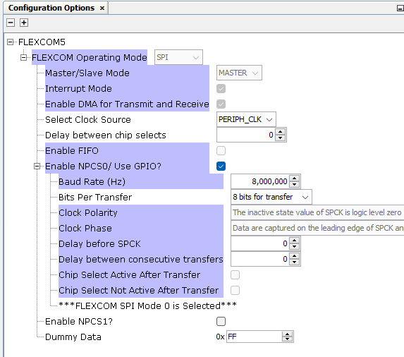
FLEXCOM5 component is auto-configured
when connected to PLC PHY component, as seen in this figure:Figure 2-14. Configure FLEXCOM5
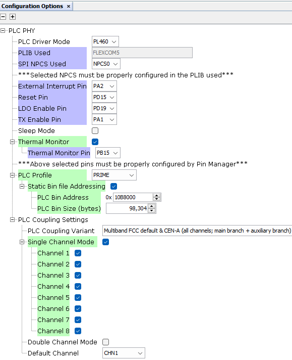
Click the PLC PHY component, on
Configuration Options set the PLC Profile to PRIME as seen in this
figure:Figure 2-15. Configure PLC PHY
Add PLC Coupling Component.
Right-click the PCOUP dependency and
select Available Satisfiers>PLC PHY Coupling (srv_pcoup)Figure 2-16. Select PLC PHY Coupling
PCOUP component is auto-configured when
added
Add Console Component.
Click the PIC32CXMTG-EK component, on Configuration Options enable the Virtual
COM Port interface on USB debugger interfaceFigure 2-17. Configure COM Port
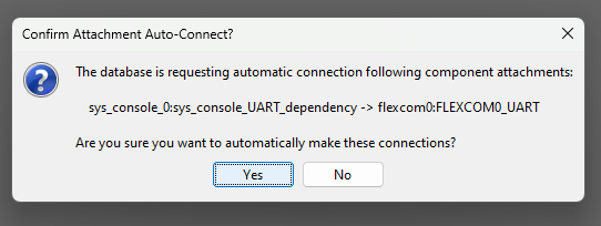
This triggers the CONSOLE and FLEXCOM0 Auto Activation and Auto ConnectionFigure 2-18. Add Console and FLEXCOM0Figure 2-19. Connect Console and
FLEXCOM0
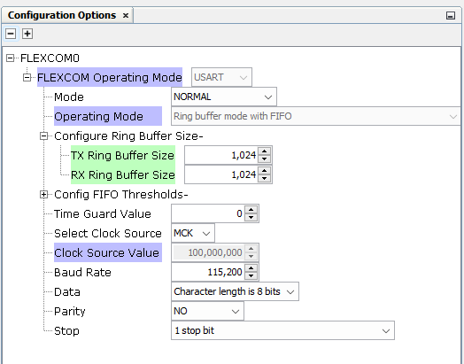
FLEXCOM0 component is auto-configured when connected to Console component, but it is
recommended to increase the Ring Buffer Size to 1024 as seen in this figure:Figure 2-20. Configure FLEXCOM0
Add Debug Component.
Right-click the SYS_CONSOLE capability
and select Consumers>DEBUG (sys_debug)Figure 2-21. Select DEBUG
DEBUG component is auto-configured when
added
Add PLC PVDD Monitor Component.
Right-click the ADC capability and
select Consumers>PLC PVDD Monitor (srv_pvddmon)Figure 2-22. Select PLC PVDD Monitor
Component
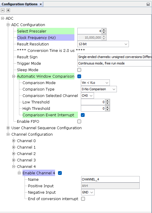
Click the ADC component, on Configuration Options set Prescaler and Channel 4
Options so configuration matches the following: Figure 2-23. Configure ADC
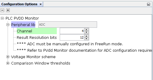
Click the PLC PVDD Monitor component, on Configuration Options set Channel 4 so
configuration matches the following: Figure 2-24. Configure PVDD Monitor
Add Time Component.
On Device Resources, navigate to System
Services and click the + sign next to TimeFigure 2-25. Add Time Component
Right-click the TMR dependency and
select Satisfiers>TC0 (tc0)Figure 2-26. Select TC0
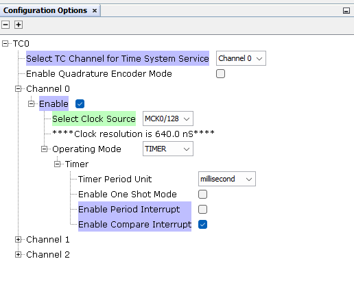
Click the TC0 component, on
Configuration Options set Clock Source to MCK0/128 on Channel 0 so
configuration matches the following: Figure 2-27. Configure TC0
Add TRNG Component.
On Device Resources, navigate to Peripherals and click the + sign next to TRNGFigure 2-28. Add TRNG
Add RF215 Component.
On Device Resources, navigate to
SmartEnergy>Drivers and click the + sign next to RF215Figure 2-29. Add RF215 Component
Right-click the SPI dependency and
select Satisfiers>FLEXCOM3 (flexcom3)Figure 2-30. Select FLEXCOM3
FLEXCOM3 component is auto-configured when connected to RF215 component
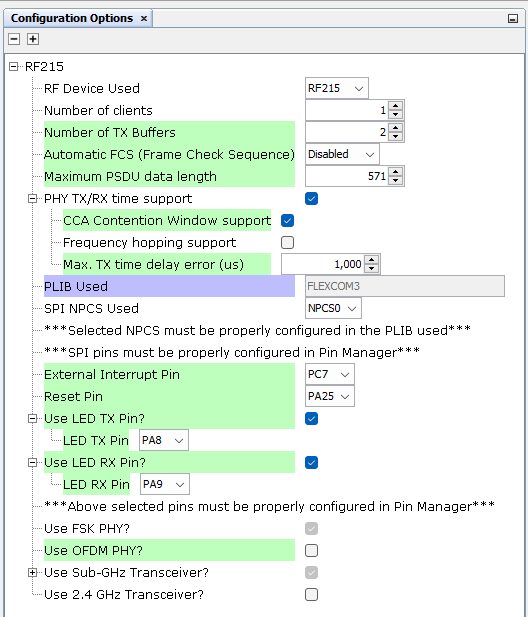
Click the RF215 component, on Configuration Options set Pins so configuration
matches the following: Figure 2-31. Configure RF215
Add Crypto Library Component.
On Device Resources, navigate to
Libraries and click the + sign next to Crypto_v4Figure 2-32. Add Crypto Library
Component
Right-click the LIB_WOLFCRYPT
dependency and select Consumers>wolfCrypt Library (lib_wolfcrypt)Figure 2-33. Select WolfCrypt
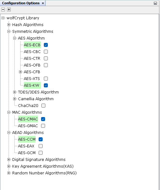
Click the wolfCrypt Library component,
on Configuration Options enable Security options required by PRIME, as seen in
this figure: Figure 2-34. Configure Crypto
Add USI Component.
On Device Resources, navigate to
SmartEnergy>Services and click the + sign next to USIFigure 2-35. Add USI Component
Right-click the UART dependency and
select Satisfiers>FLEXCOM7 (flexcom7)Figure 2-36. Select FLEXCOM7
FLEXCOM7 component is auto-configured when connected to USI component
Add Memory Component.
Right-click the SEFC0 capability and
select Consumers>MEMORY (drv_memory)Figure 2-37. Select Memory
The Memory and SEFC0 components are
auto-configured when connected to PRIME Firmware Upgrade component
Enable Leds.
Click the PIC32CXMTG-EK component, on
Configuration Options enable Green Led and Blue Led on Digital InterfaceFigure 2-38. Enable Leds
The final MCC Project Graph with the added Harmony modules should look as this:Figure 2-39. MCC Project Graph With Harmony
Modules