
12.1 Functional Description
(Ask a Question)The following figure shows the block diagram of Resolver interface.
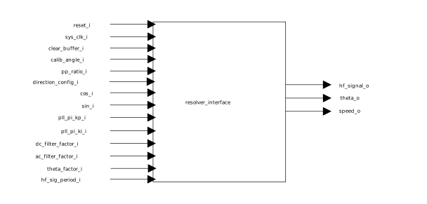
The resolver interface IP generates a square wave that is fed to the primary winding of the resolver. The frequency of the square wave can be configured through hf_sig_period_i input. The cos_i and sin_i signals from the secondary windings are demodulated and filtered to get effective cosine and sine signals. A Phase-Locked Loop (PLL) is used to extract angle and speed from cosine and sine signals.
The PLL uses a PI controller whose gains pll_pi_kp_i and pll_pi_ki_i can be tuned to get required response time. A higher value for gains results in quick response to angle and speed changes but can also induce noise in angle and speed outputs.
In motor control application, the resolver zero position must be aligned with motor magnetic zero position. To achieve this, a calib_angle_i signal is used. During calibration process, the signal goes high and the motor is forced to align its rotor to magnetic zero position. The angle output is reset to zero during this period and is taken as reference for measuring absolute angle. A motor and resolver can have multiple pole pairs in which the motor control algorithm needs multiple theta transitions (3600) for one mechanical rotation of the rotor. This feature can be configured through the pp_ratio_i port, listed in Table 12-3.
The theta_factor constant is calculated by using the following equation. The calculated speed can be scaled to per unit using theta_factor_i.
EQ1

The hf_sig_period input determines the frequency of square wave injected into resolver primary, calculated by using the following equation.
EQ2
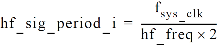
where,
hf_freq = Frequency of the square wave injected into resolver primary
fsys_clk = Frequency of the system clock provided at sys_clk_i input