
3.1 Functional Description
(Ask a Question)The following figure shows the block diagram of encoder interface.
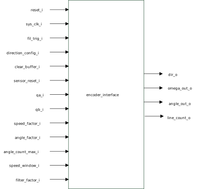
The encoder interface block converts signals received from QA, QB into its corresponding angle and speed. The block counts encoder edges till the angle_count_max_i value is attained and then starts counting from zero again. The angle generated is scaled to 262144 by multiplying it with the angle_factor_i. Speed is measured by counting the number of encoder events in a constant time period defined by speed_window_i input. A filter is used to filter the quantization noise from speed measurement. The filter time constant can be configured using the filter_factor_i value using the following equation:

The sensor_reset_i input is used to find motor electrical angle by injecting constant current for a small duration. When the motor has aligned to the injected angle, the encoder output is initialized with 90° or 270° based on initial direction of rotation. The encoder edge counting is expected to start after the falling edge of the sensor_reset_i input is detected.
The clear_buffer_i input can be used to reset the filter buffer, as the filter buffer is expected to be reset when the motor stops.
The direction_config_i input is used to initially detect the motor direction. Once the motor starts running, the motor direction is detected from the encoder signals and used in generating the angle.