3.7 Building the Example
One or more assembly source files can be built with a single execution of the
pic-as assembler driver.
readPort.S, for example, it could be built
using the command below. Note that the file name uses an upper case .S
extension so that the file is preprocessed before any other
processing.pic-as -mcpu=18f47k42 readPort.SThis command will produce (among other files) readPort.hex and
readPort.elf, which can be used by the IDE and debugger tools to
execute and debug the code. Such a command assumes that pic-as is in
your console's search path. If that is not the case, specify the full path to
pic-as when you run the application.
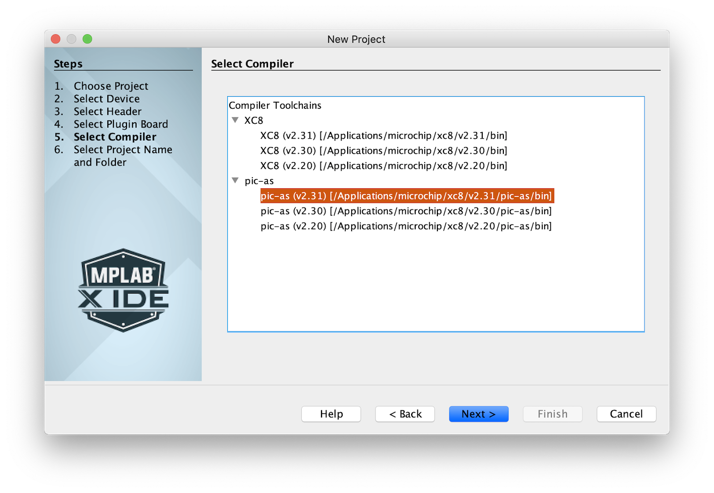
If you prefer to build in the MPLAB X IDE, create a project in the usual way. When asked
to select the compiler, choose the required version of the pic-as
toolchain. The PIC Assembler is shipped with the MPLAB XC8 C Compiler, but make sure you
choose the assembler tool, as shown in the following image.
-Wl driver option to request a map file, as shown below. (How to
specify additional options in an IDE project are given at the end of this
section.)pic-as -mcpu=18f47k42 -Wl,-Map=readPort.map readPort.SOpen readPort.map and look for the special resetVec
psect that was defined in the code. You will see something similar to the following:
TOTAL           Name                     Link     Load   Length     Space
        CLASS   CODE
                resetVec                1FFDE    1FFDE        4         0
                code                    1FFE2    1FFE2       1E         0
The resetVec psect will be present in several locations, but you can
easily find it under the CODE class, with which it was associated.
Notice that it was linked to 1FFDE, not address 0, as we require, because the linker
received no explicit placement instructions and simply linked it to a free location in
the memory defined by the CODE class. Note that it did, however, honor
the psect's reloc=2 flag and linked it to an address that was a
multiple of 2.
-A linker option) for the
CODE (and other) linker classes at the top of the map file as part
of the linker options. For this device, the definition for the CODE
class is:-ACODE=00h-01FFFFhwhich shows that this class represents one large chunk of memory from address 0 through 0x1FFFF.
Build the source file again, this time use the -Wl driver option to pass
a -p option to the linker. In the command line below, the option
explicitly places the resetVec psect at address 0.
pic-as -mcpu=18f47k42 -Wl,-Map=readPort.map -Wl,-presetVec=0h readPort.SThe content of the map file will now look similar to the following, showing that the reset code is in the correct location.
TOTAL           Name                     Link     Load   Length     Space
        CLASS   CODE
                resetVec                    0        0        4         0
                code                    1FFE2    1FFE2       1E         0
To confirm the linker's handling of the reloc psect flag, you can try
'accidentally' linking the resetVec psect to an address that is not a
multiple of 2 (for example address 0x1) using the above option.
CONFIG
directives were placed into a psect called config, which was linked to
the correct address in the hex file for this
device.TOTAL Name Link Load Length Space
...
CLASS CONFIG
config 300000 300000 A 4
-Wa,-a,
so you can explore the generated code, for
example:pic-as -mcpu=18f47k42 -Wl,-Map=readPort.map -Wl,-presetVec=0h -Wa,-a readPort.S.lst. The above
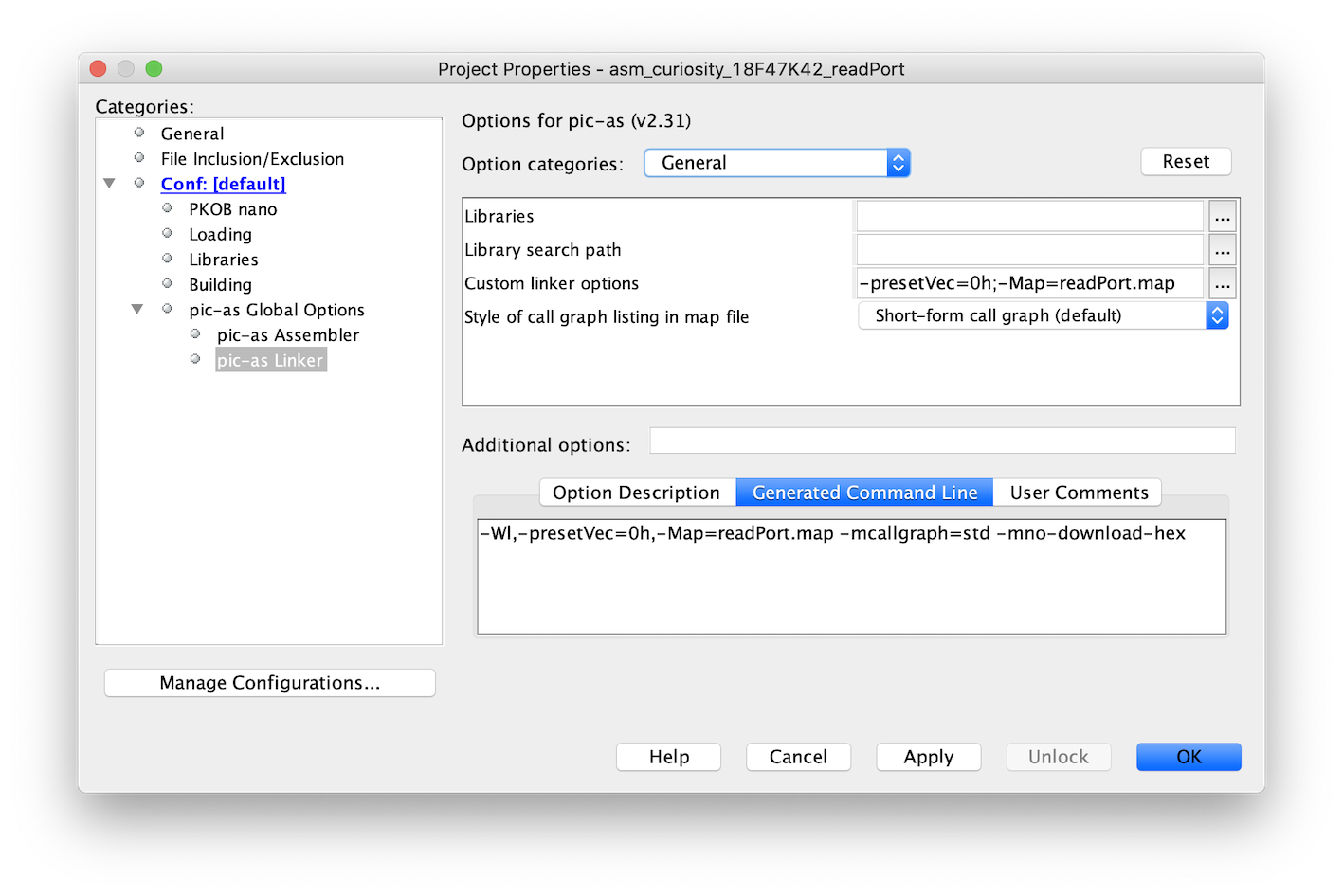
command will generate a list file called readPort.lst.If you are building in the IDE, add additional linker options (those specified above
using the driver option -Wl,linkerOption above) to the
Custom linker options field in the category in the Project Properties dialog, as shown in the following
image. When adding option to this field, do not include the leading
-Wl,, as this prefix is added in by the IDE.
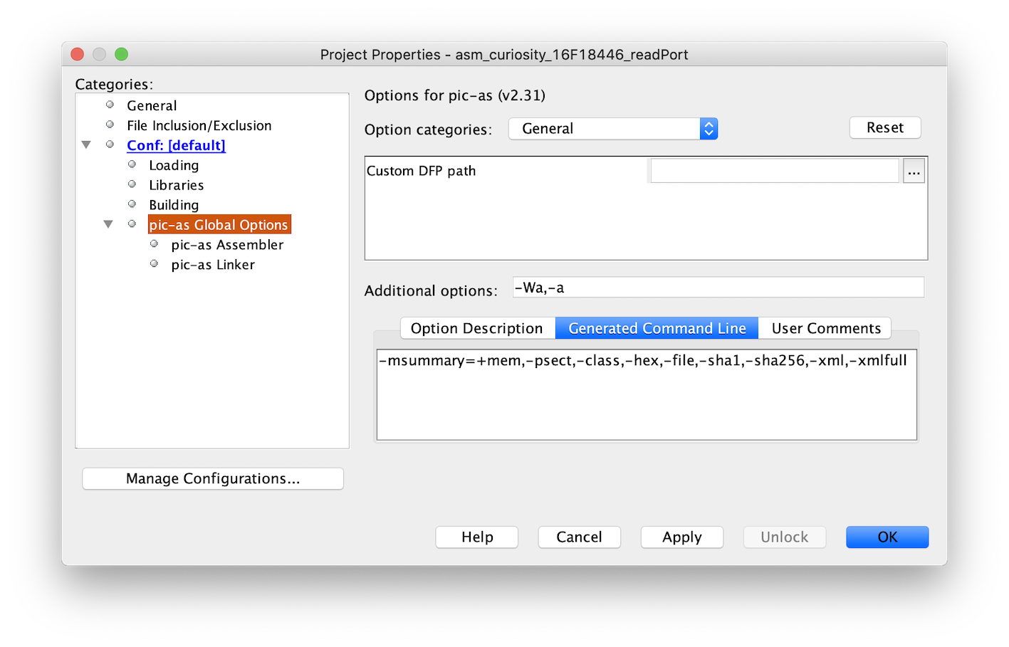
In the IDE, specify additional options to the assembler (such as the
-Wa,-a) in the Additional options field in the
pic-as Global Options category, as shown in the following
image.