The APS module implements the protocol and linear protection switching mechanisms for point-
to-point VLAN-based ETH SNC in Ethernet transport networks. APS is defined by the ITU
G.8031 standard.
The APS Configuration page allows the user to create and configure an APS Instance.
To create and configure an APS Instance, perform the following steps:
Go to Configuration > APS. The APS Configuration page appears. Figure 4-23. APS Configuration
The list of parameters in this page are as follows:
APS #: The ID of the
APS. The maximum number of creatable APS instances is 6. Click on the link
to get to APS instance page, reset counters, and issue commands.
Port: The port to
which this flow is attached
SF Trigger: Selects
whether Signal Fail (SF) comes from the link state of a given port or from a
Down-MEP
SF MEP: The Domain:
Service::MEPID refers to a MEP instance which represents the Working flow.
Only used when SF Trigger is MEP. The selected MEP instance does not need to
exist when this APS is configured.
Mode: In the linear
1:1 protection switching architecture, the protection transport entity is
dedicated to the working transport entity. However, normal traffic is
transported either on the working transport entity or on the protection
transport entity using a selector bridge at the source of the protected
domain. The selector at the sink of the protected domain selects the entity
which carries the normal traffic.
1+1
Uni: This will create a 1+1 Unidirectional APS
1+1
Bi: This will create a 1+1 Bidirectional APS
In the linear 1+1 protection switching architecture, a protection
transport entity is dedicated to each working transport entity. The
normal traffic is copied and fed to both working and protection
transport entities with a permanent bridge at the source of the
protected domain. The traffic on working and protection transport
entities is transmitted simultaneously to the sink of the protected
domain, where a selection between the working and protection transport
entities is made based on some predetermined criteria, such as server
defect indication.
Level: MD/MEG Level
(0–7)
VLAN: The VLAN ID used
in the L-APS PDUs. 0 means untagged.
PCP: PCP (priority)
(default 7). The PCP value used in the VLAN tag unless the L-APS PDU is
untagged. Must be a value in range 0–7.
SMAC: Source MAC
address used in L-APS PDUs. This must be a unicast address. If all-zeros,
the switch port's MAC address is used.
Rev: When checked, the
port recovery mode is revertive, that is, traffic switches back to the
working port after the condition(s) causing a switch has cleared. In case of
clearing a command (e. g. forced switch), this happens immediately. In case
of clearing of a defect, this generally happens after the expiry of the
Wait-To-Restore (WTR) timer. When unchecked, the port recovery mode is
non-revertive and traffic is allowed to remain on the protect port after a
switch reason has cleared.
TxAps: Choose whether
this end transmits APS PDUs. Only used for 1+1, unidirectional.
WTR: When Rev is
checked, WTR tells how many seconds to wait before restoring to the working
port after a fault condition has cleared. The valid range is 1–720.
HoldOff: When a new
(or more severe) defect occurs, the hold-off timer is started, and the event
is reported after the timer expires. HoldOff time is measured in
milliseconds, and valid values are in the range 0–10000. Default is 0, which
means immediate reporting of the defect.
Enable: The
administrative state of this APS instance. Check to make it function
normally and uncheck to make it cease functioning.
Oper: This field
cannot be configured but shows the operational state. Click on the link in
the APS
# field to get more details on the status.
– : APS
instance is functional
– : APS
instance is not functional
Warning: If the
operational state is Active, then the APS instance is active, but it might
not run
the way the administrator thinks because of configuration errors,
which are reflected/indicated in the following warnings.
– : No
warning
– : Warning
Use the tooltip to get the detailed warning
information.
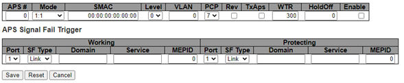
To configure the APS module, click
the + icon on the bottom right corner of the APS configuration page (see the
preceding figure). The APS Configuration table appears.Figure 4-24. APS Configuration
Table
The online versions of the documents are provided as a courtesy. Verify all content and data in the device’s PDF documentation found on the device product page.


 : APS
instance is functional
: APS
instance is functional : APS
instance is not functional
: APS
instance is not functional : No
warning
: No
warning : Warning