
5.1 Setting Up the PolarFire SoC Video and ICICLE Kit
(Ask a Question)Before running the demo, perform the following steps:
- Do not connect any Ethernet cable from the Windows Host PC to the Video Kit or ICICLE Kit.
- On the Windows Host PC, open the command
prompt in Admin mode, type the
ipconfigcommand, and press the Enter key. The command prompt window appears displaying the Windows IP configuration details as shown in the following figure.Figure 5-2. Windows Command Prompt Window in Administrator Mode 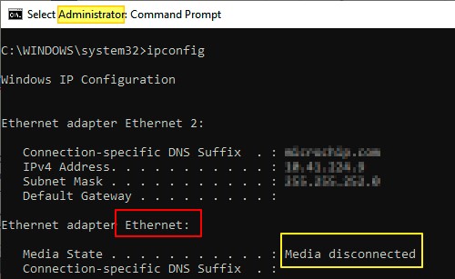
- Note down the name of the Ethernet adapter displayed against the Media disconnected interface. It is Ethernet in this case.
Video Kit Setup
To setup the Video Kit board, perform the following steps:
- Insert the dual-camera sensor module in the J10 port on the PolarFire SoC Video Kit. Ensure to remove the camera lens cap.
- Connect the RJ45 Ethernet cable to any one of the Ethernet ports (connector J6 or J7) of the board and the Windows Host PC.
- Power on the board and wait for the system boot sequence to complete.
- Log in as the root user (no password required).
- Set the IP address of the board to
192.168.2.1(or choose another address) by executing the following command in the terminal:sudo ifconfig eth0 192.168.2.1 netmask 255.255.255.0 upImportant: If your network includes a DHCP server, you may also use the IP address assigned by the DHCP server.
ICICLE Kit Setup
To setup the ICICLE Kit board, perform the following steps:
- Insert the Stepper Motor Click Board in the
Mikro Bus connector of ICICLE Kit. Make the required wire connections from Stepper Motor to
the Click Board, as shown in the following figure.
Figure 5-3. Lead Wire Configuration 
- Connect the power adapter to the click board GND and VM points. For more information on Stepper Motor, See the QMOT QSH4218 MANUAL.
- Connect the RJ45 Ethernet cable to any one of the Ethernet ports (J1 or J2) of the board and the Windows Host PC.
- Power on the board and wait for the system boot sequence to complete.
- Log in as the root user (no password required).
- Set the IP address of the board to
192.168.2.1(or choose another address) by executing the following command in the terminal:sudo ifconfig eth0 192.168.2.1 netmask 255.255.255.0 upImportant: If your network includes a DHCP server, you may also use the IP address assigned by the DHCP server.
Verifying Network Connection between the Windows Host PC and the Kits
To verify the network connection, perform the following steps:
- Ensure that the Windows Host PC is in the same network.
- In the command prompt of the Windows Host
PC, type the
ipconfigcommand, and press the Enter key. - If your computer is connected to a network with a DHCP server, note the IP address
assigned to your PC, as illustrated in the following figure.
Figure 5-4. Fetching the Ethernet Port Status 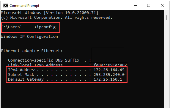
- If you prefer to manually set the IP
address, ensure to set the following as listed:
- Configure the IP address of the Windows
Host PC to
192.168.2.X, whereXis any integer between 2 and 254. - Set the Subnet mask to
255.255.255.0.
Use the following command to apply these settings:netsh interface ip set address "Ethernet" static 192.168.2.100 255.255.255.0Figure 5-5. Setting the Windows Host PC IP Address 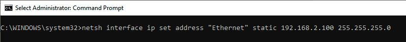
- Configure the IP address of the Windows
Host PC to
- Ping the Video Kit or ICICLE Kit from the
Windows Host PC to verify successful connection as shown in the following figure:
Figure 5-6. PolarFire SoC Video Kit or ICICLE Kit Ping Result 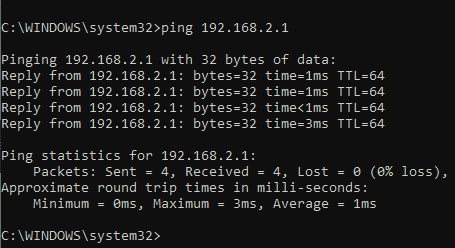
Important: For more information about connectors, jumper
settings, and other demo details, see Video Kit User Guide and ICICLE Kit User Guide.