
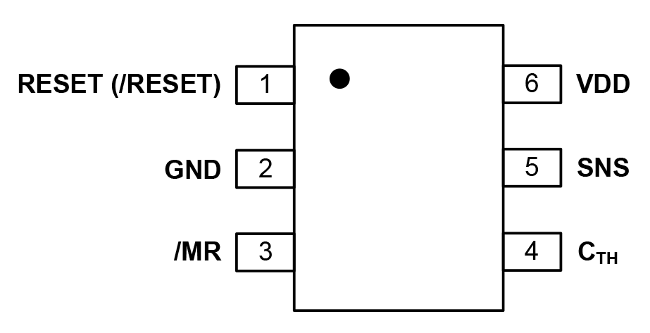
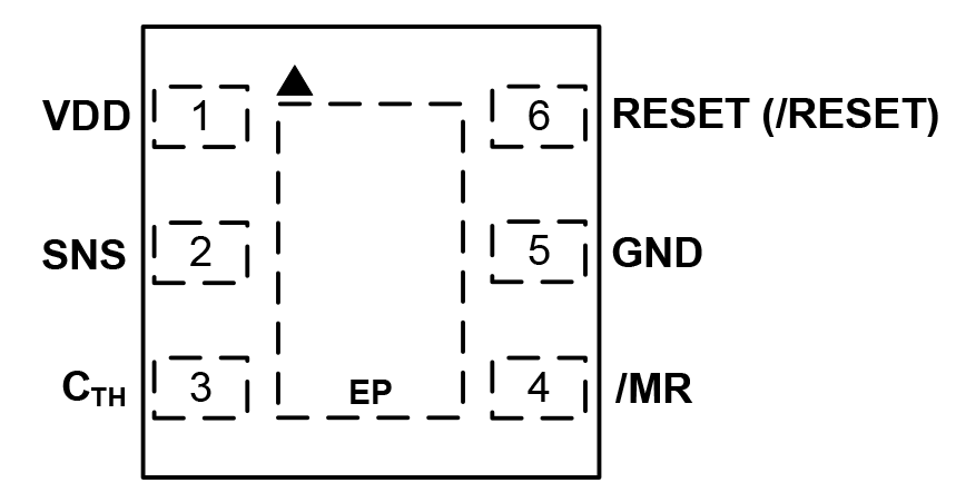
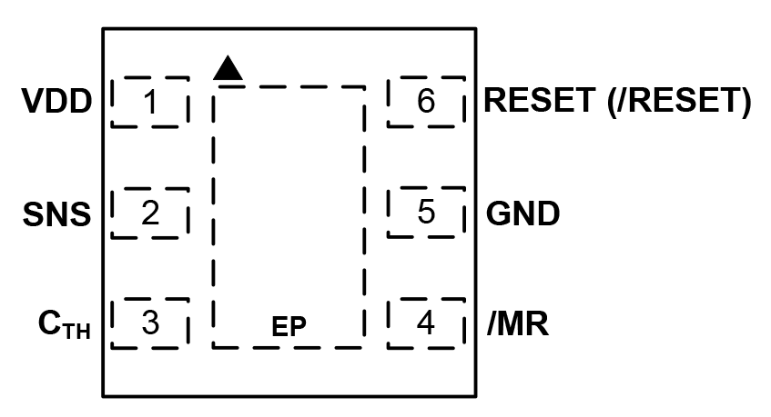
2 Pin Description
 |
 |
 |
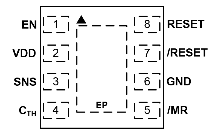 |
| Pin Number TSOT-23 (6L) | Pin Number 1.6mm x 1.6mm (6L) | Pin Number 2mm x 2mm (6L) | Pin Number 2mm x 2mm (8L) | Pin Name | Pin Function |
|---|---|---|---|---|---|
| 1 | 6 | 6 | 7 | /RESET |
/RESET is an active-low output pin and is available in an open-drain or push-pull configuration. In the open-drain configuration, a pull-up resistor to VDD is required and /RESET pin is asserted low when /MR is set to a logic low or the SNS voltage decreases below the threshold voltage. /RESET will remain low for the reset timeout delay after SNS > (VTH + VHYST) and /MR is set to a logic high. The push-pull configuration does not require a pull-up resistor and behaves exactly the same as the open-drain configuration. |
| 1 | 6 | 6 | 8 | RESET | Reset is an active-high push-pull output and is asserted high when /MR is set to a logic low or the SNS voltage decreases below the threshold voltage. RESET will remain high for the reset timeout delay after SNS > (VTH + VHYST) and /MR is set to a logic high. |
| 2 | 5 | 5 | 6 | GND | Supply Ground. |
| 3 | 4 | 4 | 5 | /MR | Manual reset is an active-low input logic level pin and is internally pulled to VDD through a 90kΩ pull-up resistor. Pulling the /MR input to a logic low asserts RESET and /RESET pins. /RESET will remain low and RESET will remain high for the reset timeout delay after /MR is pulled to logic high. |
| 4 | 3 | 3 | 4 | CTH | Programmable timeout delay. Connect a capacitor to ground to set a user-defined reset delay time. |
| 5 | 2 | 2 | 3 | SNS | Voltage monitor input. Connect the Sense pin to the voltage to be monitored through a resistor divider. When this voltage decreases below the threshold voltage, VTH, /RESET is asserted low and RESET is asserted high. |
| 6 | 1 | 1 | 2 | VDD | Supply voltage pin. Bypass with a 1µF capacitor from this pin to GND. |
| — | — | — | 1 | EN | Enable input function is only available in the MIC2793 version. This pin enables the /MR input function and RESET and /RESET outputs. When EN is in a logic low state, the reset outputs are deasserted. The EN pin has an internal 90kΩ pull-up resistor to VDD. |
| — | EP | EP | EP | ePAD | Exposed Pad. Connect to ground plane. |