4.4.1.1 Hardware Setup
Connect the Power Debugger to the PC using the USB cable. The POWER LED should turn red.
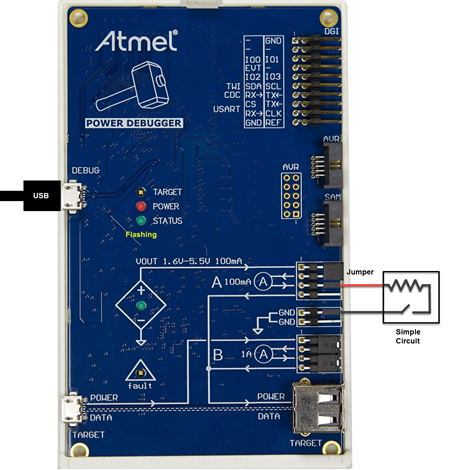
Then connect to a target. A simple connection (shown in the figure below) is used to measure circuit current by using channel A. The circuit will be powered by the debugger’s VOUT, which has been jumpered to A+. A- has been connected to the circuit. Another connection is from the circuit to board ground.
When MPLAB Data Visualizer senses the debugger and establishes communication, the STATUS LED will flash green. The level of VOUT can be set in the data visualizer and the VOUT LED will glow green.