
1.1 Features
Some key features of the dsPIC33C 4kW DC-DC Development Board are:
- Electrical specifications for a single rail:
- Input DC Voltage from 400 to 800 VDC (nominal). Over voltage protection at 950 VDC. Protected against peak voltage transients over 1000 VDC.
- Lab tested for 100A @ 12V Continuous operation and 180A @ 15V for > 10s with forced air cooling. Output current > 225A is possible with a proper cooling solution.
- Output voltage range 8-16V, with nominal voltage of 12V suitable for 12V vehicle batteries. Overvoltage protection at 18 VDC. Constant Voltage and Constant Current operations are available for battery charging.
- Nominal power output of 1200W. Continuous operation for 1700W and peak power delivery of 2700W for a short duration (10s). Note that the maximum power limit may be different depending on the cooling solution used.
- Sensing important power stage parameters, including current and voltage values for digital power control. For example, Isolated HV 800 VDC bus voltage sensing, main power transformer primary side current, output current, output voltage and high current side PCB temperature.
- Sensing inductor current to actively switch between asynchronous and synchronous rectification. Reverse current due to Inductor DCM in current-doubler topology may damage SR MOSFETs. This demonstration application has reverse current protection in firmware.
- Input side EMI filter with overcurrent protection.
- Leakage energy from the transformer due to the high secondary side currents is recirculated to the output using an additional active snubber approach. This increases total system efficiency.
- High-side short-circuit protection MOSFETs between output capacitors and 12V battery terminals provide timely and safe disconnection in case of system fault/short-circuit.
- Swappable Controller Plug-in-Modules (PIMs) to experiment with different Microchip controllers. For example, dsPIC33CK, dsPIC33CH or dsPIC33A.
- User Interface elements
- Two debug LEDs (Red and Green)
- Two push buttons (Reset and User defined)
- Auxiliary Power Supply to power on board circuitry and external interfaces.
- +12V AUX power jack for external power
- 12V, 1A SEPIC regulator for internal power
- 5V, 500 mA BUCK
- 3V3 LDO
- +20V/ -5V Bipolar Gate driver supply
- CAN-FD Interface for remote control through PC application. Microchip offers the Power Board Visualizer application for controlling similar power converters. Users may also explore X2C-based solutions for remote monitoring.
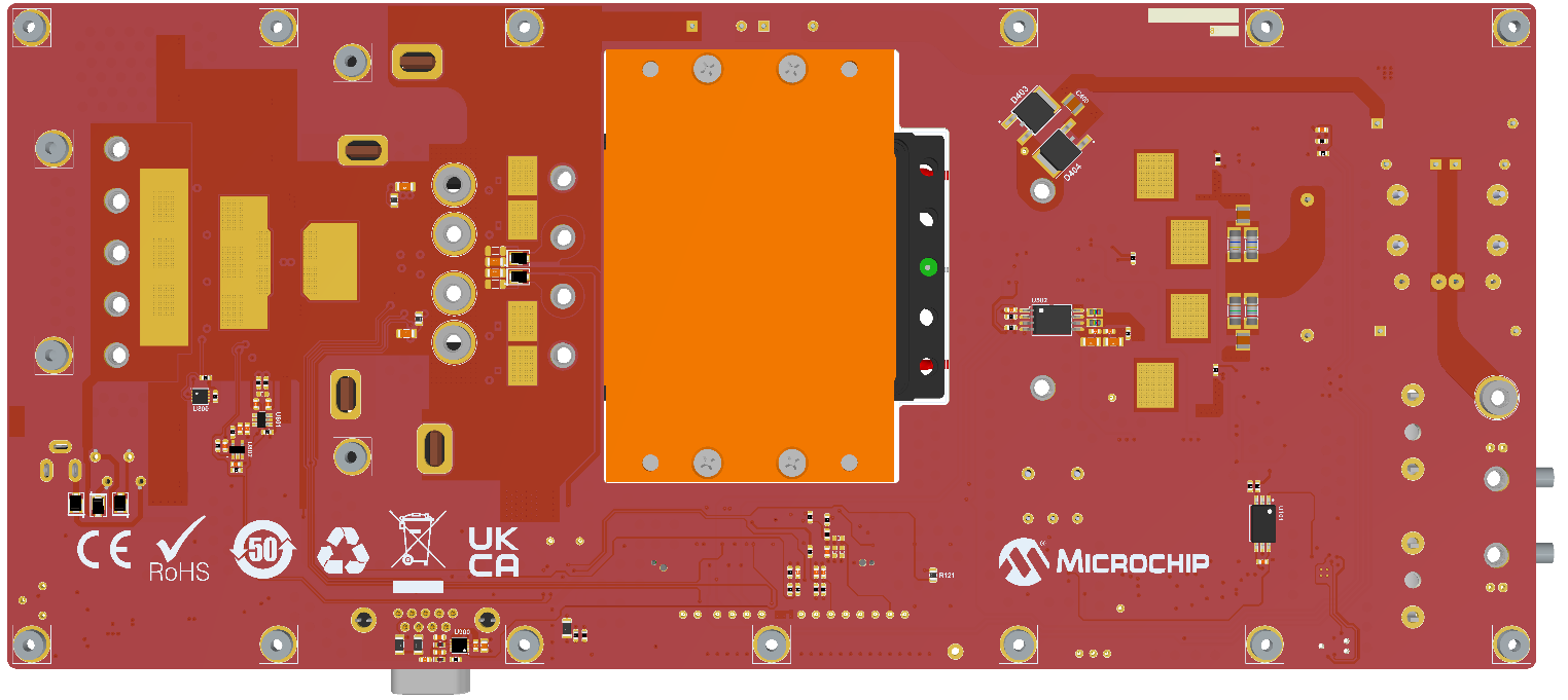
| Mark | Subcircuit |
|---|---|
1 | Input power connector and VIN sense lines (400V-800V DC Input) |
2 | 5A, 1000V Fuse |
3 | Input EMI Filter |
4 | Shim Inductance for ZVS operation |
5 | 4kV Isolated VIN sense sub-circuit (PIC16F1764 based) |
6 | 4kV Isolated Gate driver supply |
7 | 4kV Isolated Current Transformer, 1:100 |
8 | Voltage and Current loop measurement; Bode Injection points. |
9 | Signal probing and test points |
10 | HMI: Reset and User buttons and status LEDs |
11 | 4 kV Isolated Microchip Gate drivers (MCP14C) |
12 | 1200V 80 mΩ Microchip SiC |
13 | Digital Power Plug-In-Module, dsPIC33CK |
14 | Active Snubber Circuit |
15 | CAN Bus Connector for CAN-FD |
16 | 5V, 500mA Microchip SMT drop-in Buck converter module |
17 | 12V, 1A SEPIC |
18 | AUX 12V 1A 2.1mm Jack for development and testing |
19 | 100V, 296A Synchronous MOSFETs 2.53 mΩ |
20 | Non-Isolated Microchip Gate drivers (MCP14A0452) |
21 | 0.1 mOhm 18W Shunt for the secondary side current sense amplifier |
22 | Short-circuit switch circuity for protection against battery shorts |
23 | Output Connectors (REDCUBE 5x50A) can deliver up to 250A. |