
3.8 Rectification (Synchronous vs Asynchronous)
Asynchronous rectification is useful in light load operation. As discussed earlier, DCM may lead to reverse inductor current and high voltage spikes at the drain of the Synchronous Rectifier MOSFETs. Asynchronous rectification stops any reverse currents into the SR MOSFETs, except for reverse recovery currents in the body diodes.
The following limits are used to enable synchronous rectification by sensing combined output inductor current.
- Rising current limit, I_SEC_AVG_FILT ≥ 34A, turns ON synchronous rectification.
- Falling current limit, I_SEC_AVG_FILT ≤ 30A, turns OFF synchronous rectification.
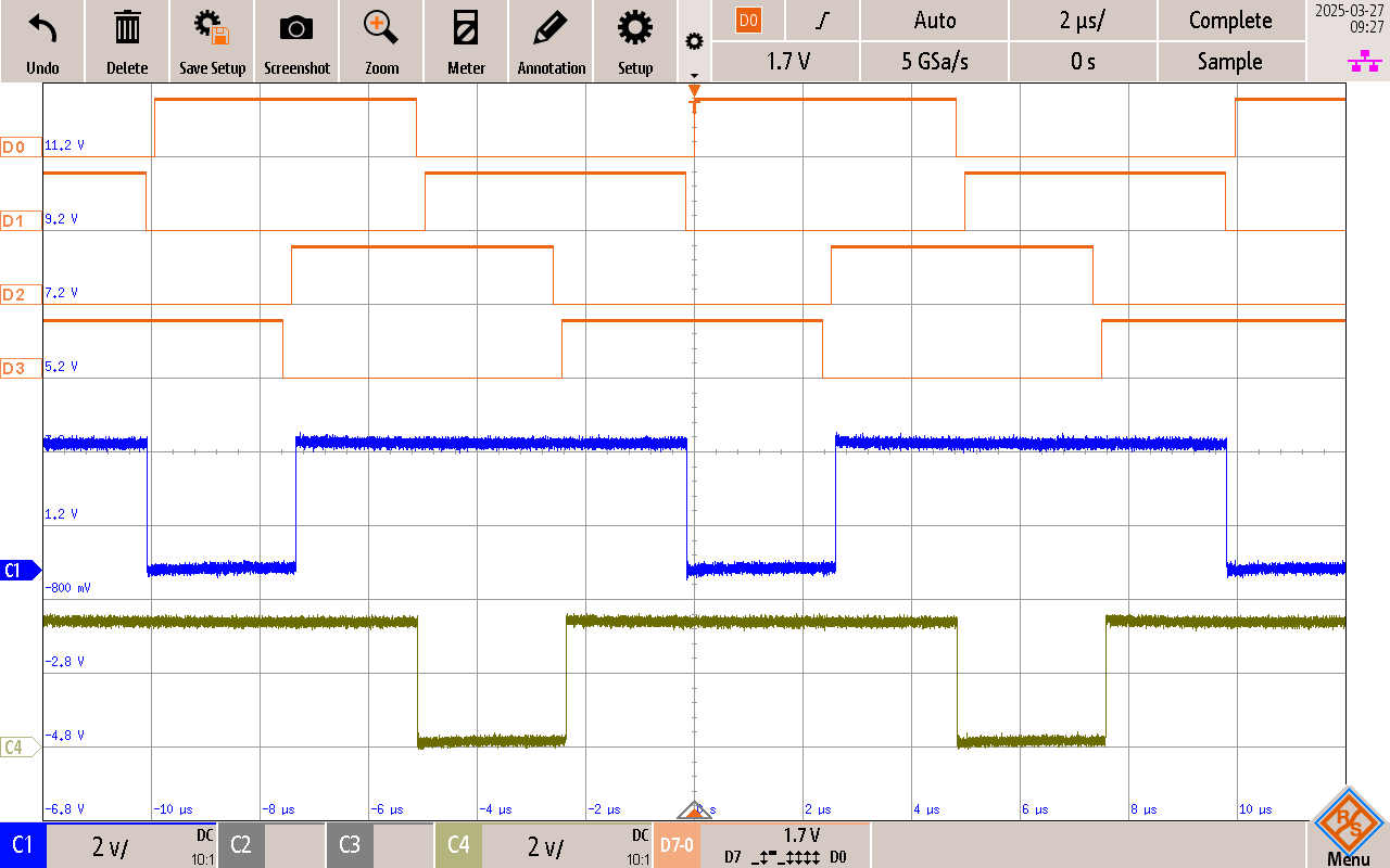
Channel details:
Channel 1: SR1 CTRL Signal
Channel 4: SR2 CTRL Signal
Digital CH-0: D0 control for HSS1 Digital CH-1: D1 control for LSS1
Digital CH-2: D2 control for HSS2
Digital CH-3: D3 control for LSS2
Synchronous rectification reduces conduction losses at higher current. Similar to a buck converter, the SR MOSFET turns OFF only when power is being transferred from input and stays ON the rest of the time, freewheeling the energy stored in output inductors.
An analysis of SR MOSFET covered in detail in the operational manual shows how SR MOSFETs operate in soft switching in PSFB-CDR. Therefore, switching losses are negligible. Main losses in SR MOSFETs come from conduction loss and a small amount of power loss comes from body diode conduction during dead time and reverse recovery loss.
ZVS and ZCS (Zero-Current-Switching) can be observed on SR Turn ON due to the commutation phase which forces zero voltage at SR drain-source and causes circulating currents at the primary side.