
3.2 PSFB-CDR Commutation Phases in Detail
|
|
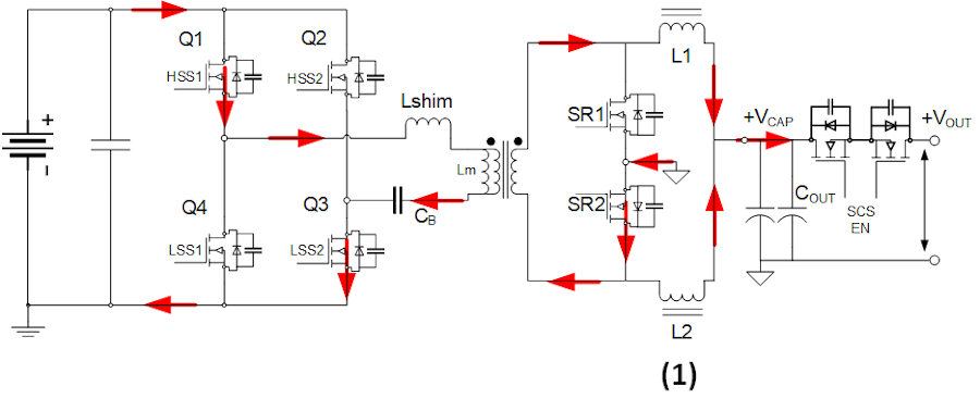
PHASE-1: Q1, Q3 diagonal is in ON state and is conducting. This applies, +VIN at XFR. Q2, Q4 are in OFF state. SR2 is in ON state and is conducting. SR1 is in OFF state. L1, L2 conduct ‘Io/2’ current. SR2 conducts roughly ‘Io’ during this phase. |
|
|
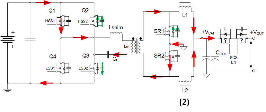
PHASE-2: Q1 is in ON state. Q3 is switched OFF. Coss of Q3 charges. Current starts to flow through Q2 body diode and discharges Q2 Coss. XFR primary voltage swings to 0V. SR2 is in ON state and is conducting. Current starts to flow through SR1 Body diode and discharges SR1 Coss. |
|
|
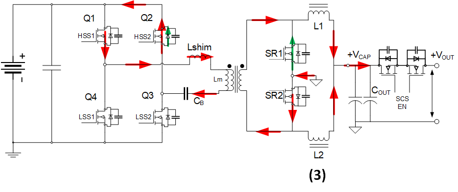
PHASE-3: Q1 is in ON state. Q2 is switched ON with ZVS. Q4 and Q3 are in OFF state. XFR primary voltage becomes 0V and XFR current becomes constant as circulating currents (decreases slowly showing circulating losses). SR2 is still conducting approximately ‘Io’. XFR secondary current does not change. SR1 is switched ON with ZVS and ZCS. |
|
|
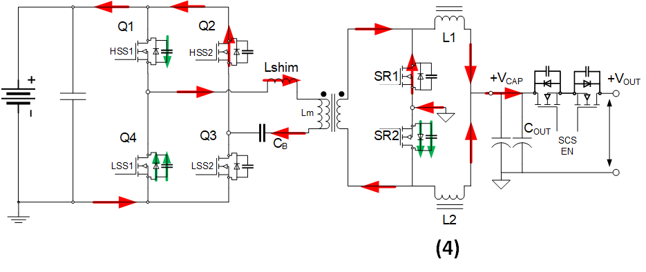
PHASE-4: Q2 is in ON state. Q1 is switched OFF. Q1 Coss charges. Current starts flowing through Q4 body diode and discharges Coss. XFR primary voltage swings towards negative VIN. SR2 is switched OFF and SR1 is now conducting approximately ‘Io’. |
|
|
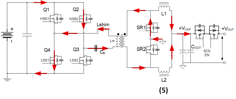
PHASE-5: Q2 is in ON state. Q4 is switched ON. Q1 and Q3 are OFF. XFR primary voltage is now -VIN. SR2 body diode is reverse biased. SR1 is ON and conducting ‘Io’. |
|
|
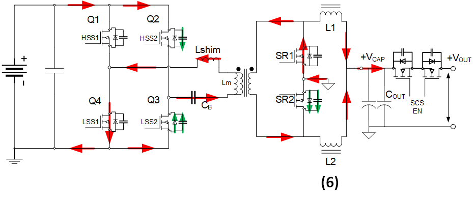
PHASE-6: Q4 is ON and conducting. Q2 is switched OFF. Q2 Coss discharges and current starts to flow through Q3 body diode and Coss is discharged. XFR primary voltage swings to 0V. SR1 is in ON state and is conducting. Current starts to flow through SR2 Body diode and discharges Coss. |
|
|
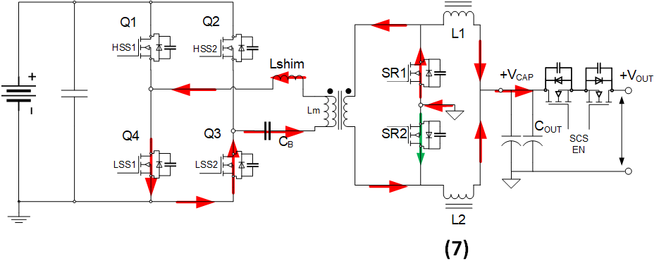
PHASE-7: Q4 is in ON state. Q3 is switched ON with ZVS. Q1 and Q2 are in OFF state. XFR primary voltage becomes 0V and XFR current becomes constant as circulating currents (decreases slowly showing circulating losses). SR1 is still conducting approximately ‘Io’. XFR secondary current does not change. SR2 is switched ON with ZVS and ZCS. |
|
|
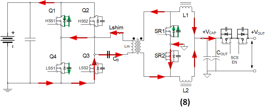
PHASE-8: Q3 is in ON state. Q4 is switched OFF. Q4 Coss charges. Current starts flowing through Q1 body diode and discharges Coss. XFR primary voltage swings towards positive VIN. SR1 is switched OFF and SR2 is now conducting approximately ‘Io’. |
| PHASE | Q1 | Q2 | Q3 | Q4 | SR1 | SR2 |
|---|---|---|---|---|---|---|
Phase-1 | ON | OFF | ON | OFF | OFF | ON |
Phase-2 | ON | OFF | OFF | OFF | OFF | ON |
Phase-3 | ON | ON | OFF | OFF | ON | ON |
Phase-4 | OFF | ON | OFF | OFF | ON | OFF |
Phase-5 | OFF | ON | OFF | ON | ON | OFF |
Phase-6 | OFF | OFF | OFF | ON | ON | OFF |
Phase-7 | OFF | OFF | ON | ON | ON | ON |
Phase-8 | OFF | OFF | ON | OFF | OFF | ON |