2 I2C Host Example Component, Running the Examples
2.1 Running the I2C Host - Find all Clients Example
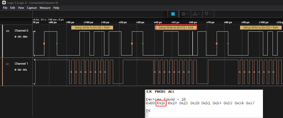
In this example, an I2C write is attempted for all possible I2C client addresses, looking for all clients which respond with an ACK. This builds up a list of valid I2C_Client addresses on the bus, displaying this as a printf message over the UART. The example uses a polled implementation.
In the Prinft with Error Checking visualization output, as each address is attempted, an ACK or NACK message is printed over the UART.
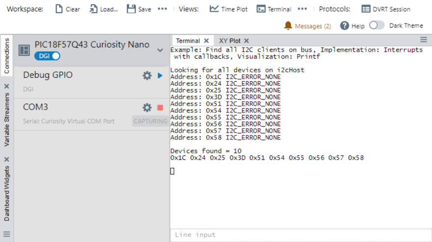
When using the MPLAB® Data Visualizer, after configuring the Terminal to 115200 'displaying as text in the terminal' the example will look as follows when run.
Below is a still image of the result one gets after running the Find all I2C clients on bus example. A a write is attempted for all possible I2C client addresses, looking for all clients which respond with an ACK, i.e., I2C_ERROR_NONE.

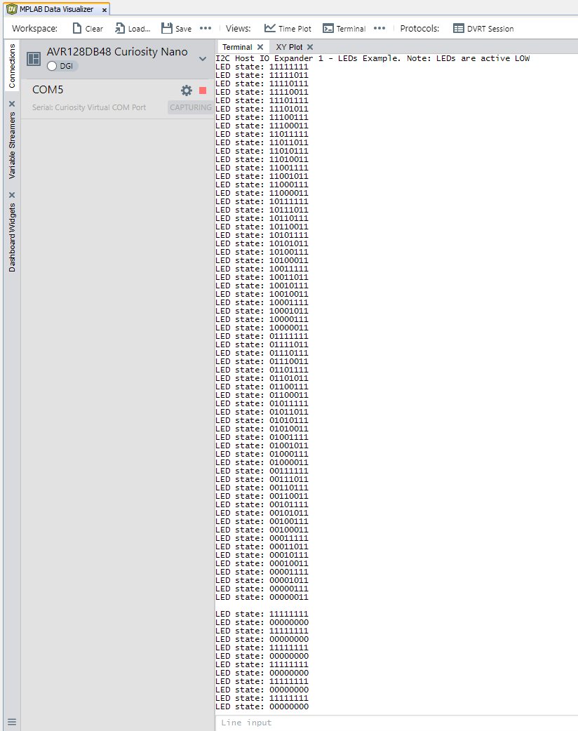
2.2 Running the I2C Host IO Expander 1 - LEDs Example
The example implements a LED chaser, incrementing the binary number on the lower six LEDs every 100 ms. Once the six active LOW LEDs are all on, the pattern changes to toggle all eight LEDs every second.
- The polled implementation uses the Delay Driver, displaying the hex and binary value of the I/O expander pins as a printf message over the uart.
-
The callbacks implementation uses the Timer Driver. To handle the change from 100 to 1000 ms, the timer period is changed and a new timer callback is used. The hex and binary values of the I/O expander pins are displayed as a printf message over the UART.
2.3 Running the I2C Host IO Expander 2 - LEDs and Buttons Example
On the Curiosity Nano Explorer, the pins on the I2C I/O Expander 1 are connected to active LOW LEDs, while the pins on the I2C I/O Expander 2 are connected to buttons (SW1, SW2 and SW3) as well as the JOYSTICK inputs (Left, Right, Up, Down, Press).
This example configures I/O Expander 1 pins as outputs set LOW, so the active low LEDs are initially all turned on. The I/O Expander 2 pins are configured as digital inputs. As a BUTTON press, or JOYSTICK input is detected, the associated LED is turned off. The Curiosity Nano's SW is configured as a reset, turning on all the LEDs again.
When using the MPLAB Data Visualizer, after configuring the MPLAB® Data Visualizer Terminal to 115200 and 'displaying as text in the terminal' the example will look as follows when run.
2.4 Running the I2C Proximity Sensor Example
This example reads the value of the VCNL4200 proximity sensor, on the Curiosity Nano Explorer, then depending on which Visualization Output is selected, sends the appropriatly formated value to the MPLAB Data Visualizer, i.e., depending on whether Printf (with error handling), Data Streamer or DV Run Time is selected as the visualization output, the following variations can be displayed on the Data Visualizer.
Printf (with Error Handling)
After configuring the MPLAB® Data Visualizer Terminal to 115200 and 'displaying as text in the terminal' the example will look as follows when run.
Data Streamer
After configuring the MPLAB® Data Visualizer Data Streamer the example will look as follows when run.
DV Run Time
After configuring the MPLAB® Data Visualizer DV Run Time the example will look as follows when run.