
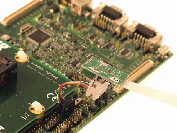
3.5 Connecting to an SPI Target
The pinout for the 6-pin SPI connector is shown in Figure 4-7.
Be sure to use the correct orientation of the 6-pin header when connecting the Atmel AVR JTAGICE mkII to the target application PCB.
Note: The SPI interface is effectively disabled when the debugWIRE enable fuse (DWEN) is
programmed, even if SPIEN fuse is also programmed. To re-enable the SPI interface, the
'disable debugWIRE' command must be issued while in a debugWIRE debugging session.
Disabling debugWIRE in this manner requires that the SPIEN fuse is already programmed.
If Atmel Studio fails to disable debugWIRE, it is probable that the SPIEN fuse is NOT
programmed. If this is the case, it is necessary to use a high-voltage programming
interface to program the SPIEN fuse. It is HIGHLY ADVISED to simply let Atmel Studio
handle setting and clearing of the DWEN fuse.
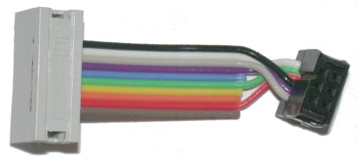
| JTAGICE mkII probe | Target pins | Squid cable colors | SPI pinout |
|---|---|---|---|
| Pin 1 (TCK) | SCK | Black | 3 |
| Pin 2 (GND) | GND | White | 6 |
| Pin 3 (TDO) | MISO | Grey | 1 |
| Pin 4 (VTref) | VTref | Purple | 2 |
| Pin 5 (TMS) | Blue | ||
| Pin 6 (nSRST) | RESET | Green | 5 |
| Pin 7 (Vsupply) | Yellow | ||
| Pin 8 (nTRST) | Orange | ||
| Pin 9 (TDI) | MOSI | Red | 4 |
| Pin 10 (GND) | Brown |