
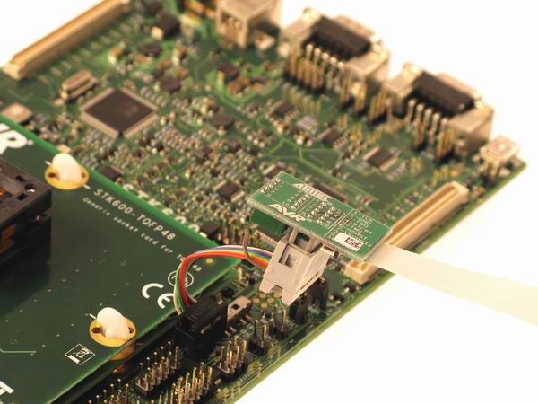
3.3 Connecting to a debugWIRE Target
The pinout for the 6-pin debugWIRE (SPI) connector is shown in Figure 4-6.
Be sure to use the correct orientation of the 6-pin header when connecting the Atmel AVR JTAGICE mkII to the target application PCB.
Although the debugWIRE interface only requires one signal line (RESET), VCC, and GND to operate correctly, it is advised to have access to the full SPI connector so that the debugWIRE interface (DWEN fuse) can be enabled and disabled using SPI programming.
Some precautions regarding the RESET line must be taken to ensure proper communication over the debugWIRE interface. If there is a pull-up resistor on the RESET line, this resistor must be larger than 10kΩ. The JTAGICE mkII has an internal RESET pullup. Any capacitive load on the RESET line should be removed. Any other logic connected to the RESET line should also be removed.
When the DWEN fuse is enabled the SPI interface is overridden internally in order for the OCD module to have control over the RESET pin. The debugWIRE OCD is capable of disabling itself temporarily (using the button on the debugging tab in the properties dialog in Atmel Studio), thus releasing control of the RESET line. The SPI interface is then available again (only if the SPIEN fuse is programmed), allowing the DWEN fuse to be un-programmed using the SPI interface. If power is toggled before the DWEN fuse is un-programmed, the debugWIRE module will again take control of the RESET pin. It is HIGHLY ADVISED to simply let Atmel Studio handle setting and clearing of the DWEN fuse.
It is not possible to use the debugWIRE Interface if the lockbits on the target AVR are programmed. Always be sure that the lockbits are cleared before programming the DWEN fuse and never set the lockbits while the DWEN fuse is programmed. If both the debugWIRE enable fuse (DWEN) and lockbits are set, one can use High Voltage Programming to do a chip erase, and thus clear the lockbits. When the lockbits are cleared the debugWIRE Interface will be re-enabled. The SPI Interface is only capable of reading fuses, reading signature and performing a chip erase when the DWEN fuse is un-programmed.
| JTAGICE mkII probe | Target pins | Squid cable colors | SPI pinout |
|---|---|---|---|
| Pin 1 (TCK) | SCK | Black | 3 |
| Pin 2 (GND) | GND | White | 6 |
| Pin 3 (TDO) | MISO | Grey | 1 |
| Pin 4 (VTref) | VTref | Purple | 2 |
| Pin 5 (TMS) | Blue | ||
| Pin 6 (nSRST) | RESET | Green | 5 |
| Pin 7 (Vsupply) | Yellow | ||
| Pin 8 (nTRST) | Orange | ||
| Pin 9 (TDI) | MOSI | Red | 4 |
| Pin 10 (GND) | Brown |