
3.2 Connecting to a PDI Target
The pinout for the 6-pin PDI connector is shown in Figure 4-5.
If your unit is revision 0, then PDI programming and debugging is not possible using this hardware. The JTAG interface (if available on your target device) does however provide the same functionality as PDI, although it uses I/O pins on the target device.
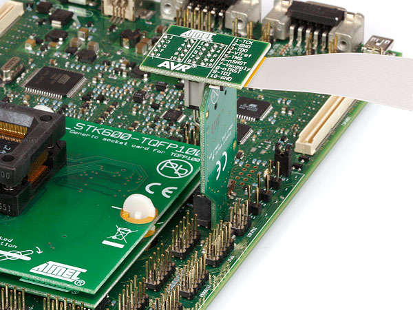
The pinout shown above is supported natively by the Atmel STK®600 as well as all future Atmel AVR XMEGA capable tools. In order to use the JTAGICE mkII with this pinout, it is necessary to make use of the XMEGA PDI adapter for JTAGICE mkII, which is available from your local Atmel representative.
Alternatively, the PDI interface can be connected using the multicolored "squid" cable, which is shipped with the JTAGICE mkII kit.
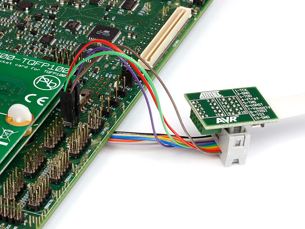
When connecting to a target that does not have the standard 6-pin header, you can use the squid cable between the JTAGICE mkII 10-pin JTAG connector on the probe and the target board. Four connections are required, and the table below describes where to connect them.
| JTAGICE mkII probe | Target pins | Squid cable colors | STK600 PDI pinout |
|---|---|---|---|
| Pin 1 (TCK) | Black | ||
| Pin 2 (GND) | GND | White | 6 |
| Pin 3 (TDO) | Grey | ||
| Pin 4 (VTref) | VTref | Purple | 2 |
| Pin 5 (TMS) | Blue | ||
| Pin 6 (nSRST) | PDI_CLK | Green | 5 |
| Pin 7 (Not connected) | Yellow | ||
| Pin 8 (nTRST) | Orange | ||
| Pin 9 (TDI) | PDI_DATA | Red | 1 |
| Pin 10 (GND) | Brown |