5.2 MCC Melody Example Components: Running the Examples
5.2.1 ADCC Example - PIC16F/18F
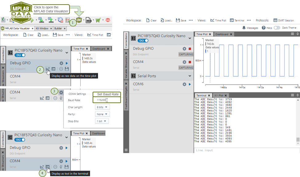
5.2.1.1 Running the ADCC Basic Printf Example
When using the MPLAB Data Visualizer Time Plot to run the ADCC Basic Printf example, the following will appear:
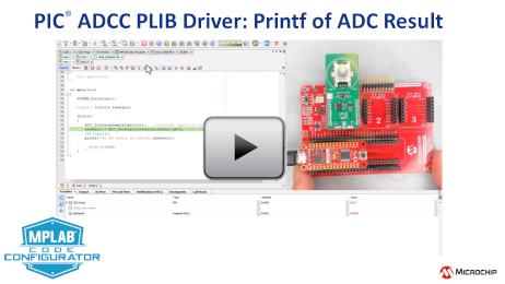
The following video shows a similar example from the MCC Melody API Reference for PIC16F/18F MCU Families.
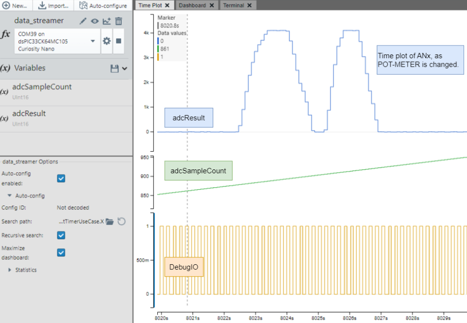
5.2.1.2 Running the ADCC Data Streamer Example
When using the MPLAB Data Visualizer Time Plot to run the ADCC Basic Printf example, the following will appear:
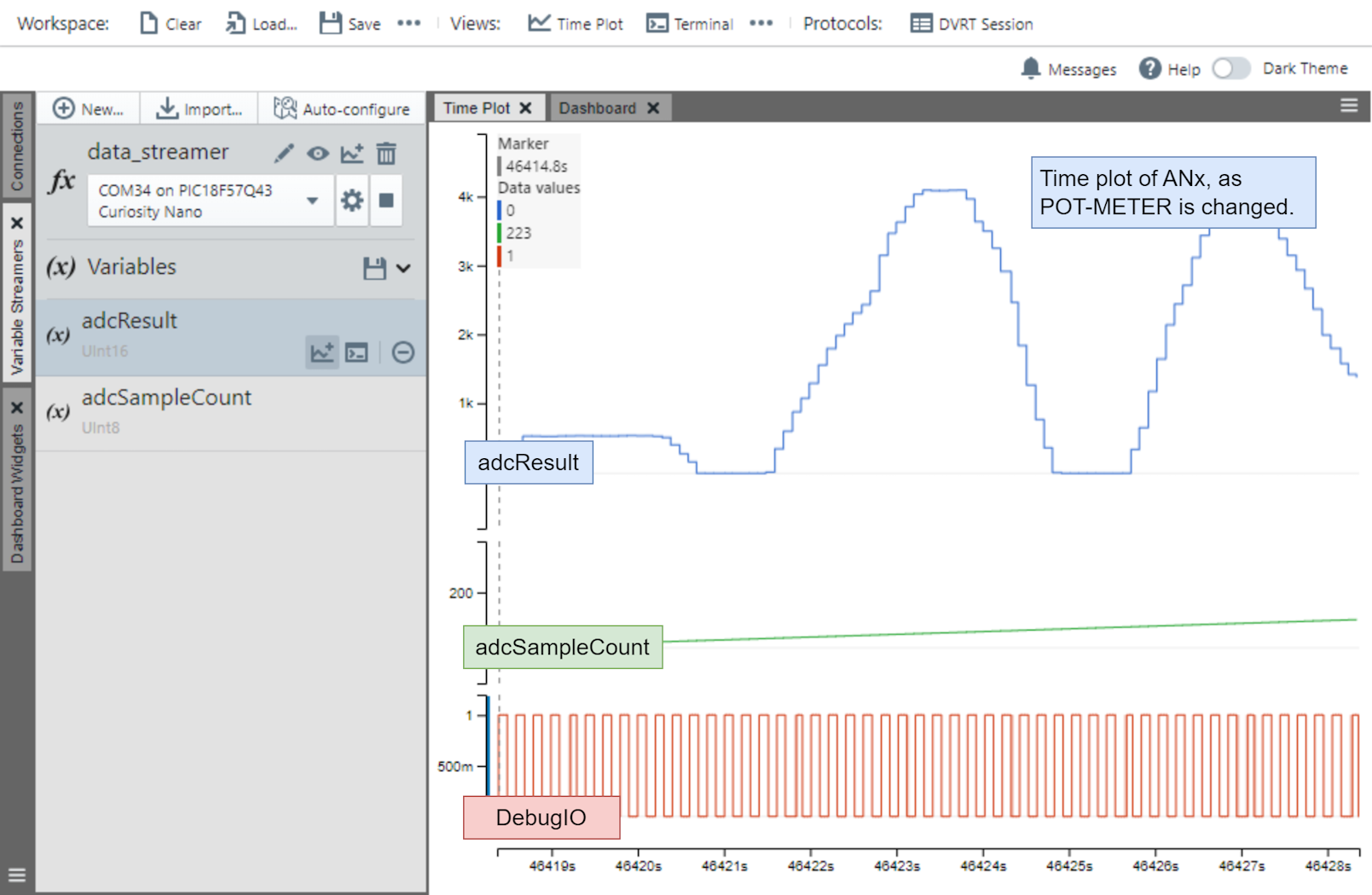
data_streamer.ds, meaning the Data Streamer variable configuration
file, as follows: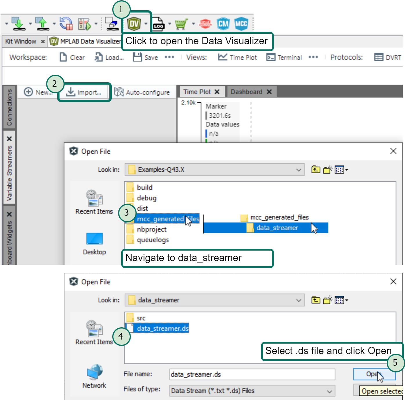
The following video shows a similar example from the MCC Melody API Reference for PIC16F/18F MCU Families.
5.2.1.3 Running the ADCC Spike Detection Example
adcResult_lastSpike and adcSpikeCount
variables.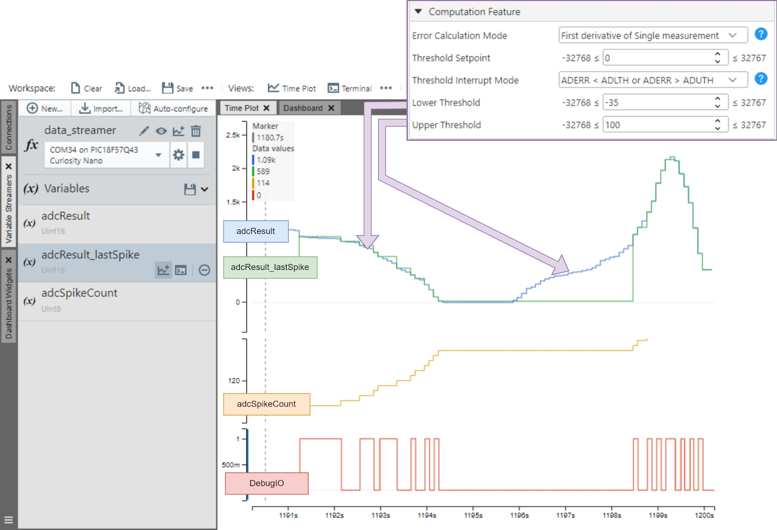
The following video shows a similar example from the MCC Melody API Reference for PIC16F/18F MCU Families.
5.2.1.4 Example Board for the ADCC Examples
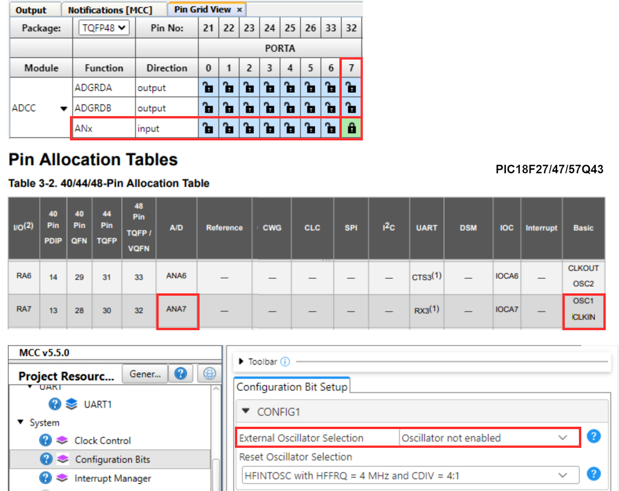
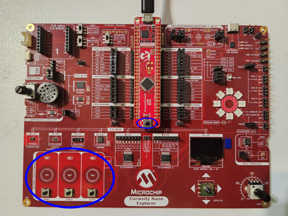
The ADCC example can be run on Curiosity Nano boards, such as the PIC18F-Q41 or PIC18F-Q43. The image below shows an ADC reading of the Q43, taken by using the potentiometer on the Curiosity Nano Explorer.
All three ADCC examples were tested using the hardware setup presented below.
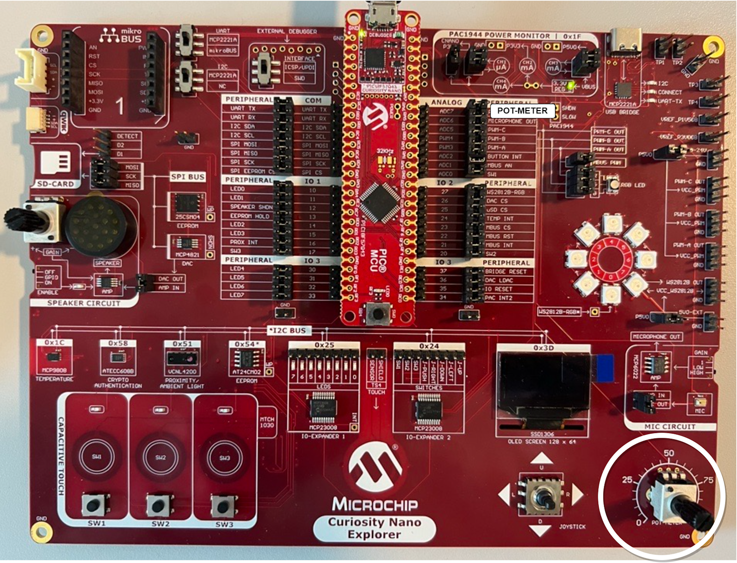
Some MCUs, such as the Q41 and Q43, have CLKIN on ANA7. So that this does not conflict with the POT on the CNano Explorer, disable the External Oscillator in System>Configuration Bits.
5.2.2 ADC Example - dsPIC
5.2.2.1 Running the ADC Basic Printf Example
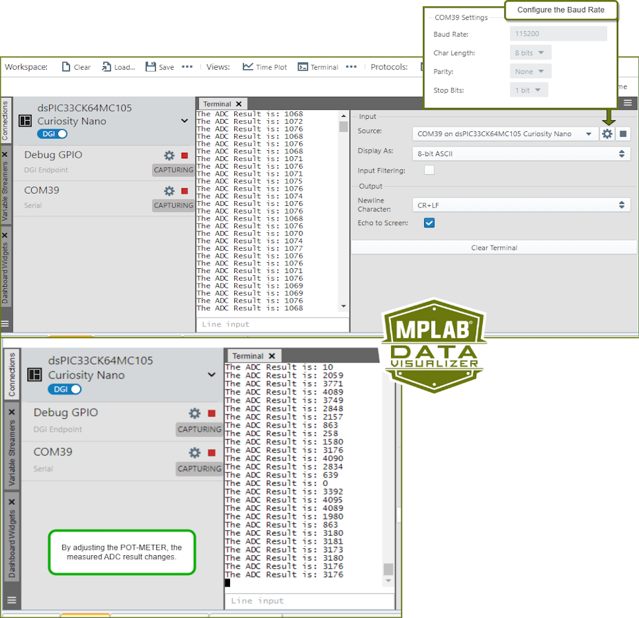
When using the MPLAB Data Visualizer Time Plot to run the ADC Basic Printf example, the following will appear:
The following video shows a similar example from the MCC Melody API Reference for PIC16F/18F MCU Families.
5.2.2.2 Running the ADC Data Streamer Example
When using the MPLAB Data Visualizer Time Plot to run the ADC Basic Printf example, the following will appear:
The following video shows a similar example from the MCC Melody API Reference for PIC16F/18F MCU Families.
data_streamer.ds, meaning the Data Streamer variable configuration
file, as follows:
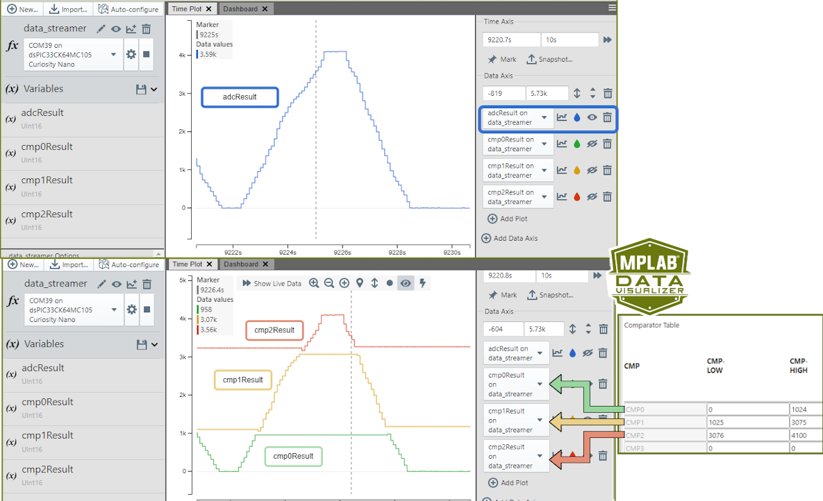
5.2.2.3 Running the ADC Comparator Example
There are four values that can be displayed by the Data Streamer:
- adcResult - The total ADC result over time
- cmp0Result - The ADC value updated when a CMP0 interrupt occurs
- cmp1Result - The ADC value updated when a CMP1 interrupt occurs
- cmp2Result - The ADC value updated when a CMP2 interrupt occurs
The CMP interrupts occur when an ADC result read in is within the threshold defined in the Comparator Settings LOW and HIGH values.
In the image below, the top section plots the full ADC value of the
adcResult variable, in the lower section the CMP values are plotted
together to show that these values are updated only when its within each threshold value
defined.
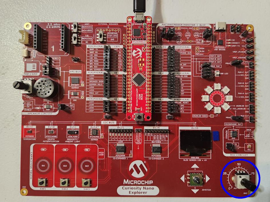
5.2.2.4 Example Board for the ADC Examples
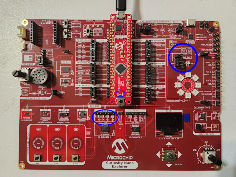
The ADC example can be run on Curiosity Nano boards, such as the dsPIC33CK64MC105. In the image below the dsPIC is taking ADC readings from the potentiometer on the Curiosity Nano Explorer.
All three ADC examples were tested using the hardware setup presented below.
5.2.3 UART Example - PIC16F/18F, AVR
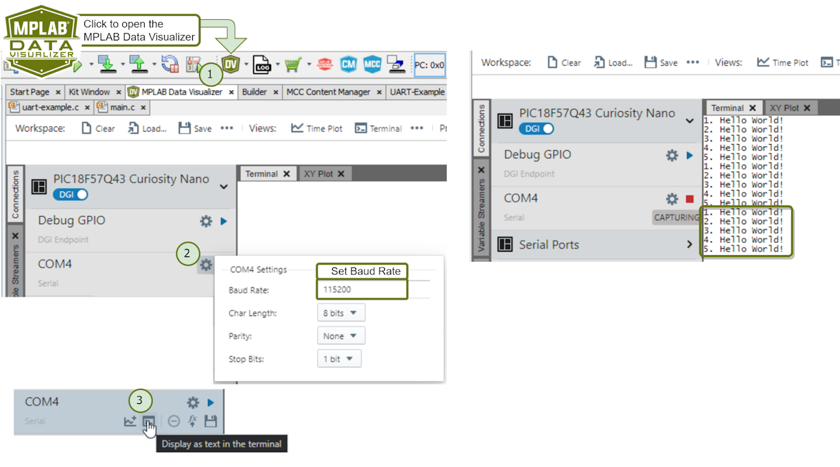
5.2.3.1 Running the UART Printf Variable Counter Example
This example uses printf to print: “x Hello World!” to a terminal, where x is a counter. When using the MPLAB Data Visualizer Terminal to run the UART Printf Variable Counter example, the following will appear:
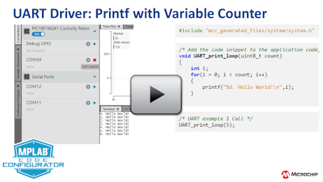
The following video shows a similar example from the MCC Melody API Reference for: PIC16F/18F, AVR.
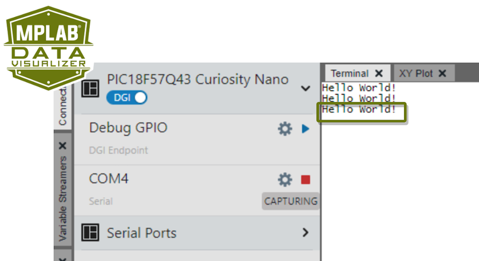
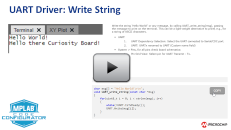
5.2.3.2 Running the UART Write String
Write any message by calling UART_write_string(msg), passing the message
to print on the terminal. This can act as a light-weight alternative to printf. Running
the UART Write String example displays the “Hello World!” message in the terminal.
The following video shows a similar example from the MCC Melody API Reference for: PIC16F/18F, AVR.
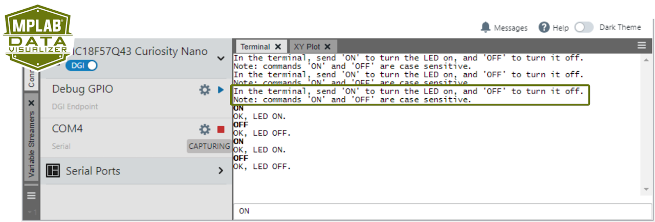
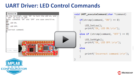
5.2.3.3 Running the UART Control Commands
This example shows how to implement a basic Command Line Interface (CLI). Here a LED is controlled using commands from a terminal. Send “ON” to turn the LED on, and “OFF” to turn it off.
The following video shows a similar example from the MCC Melody API Reference for: PIC16F/18F, AVR.
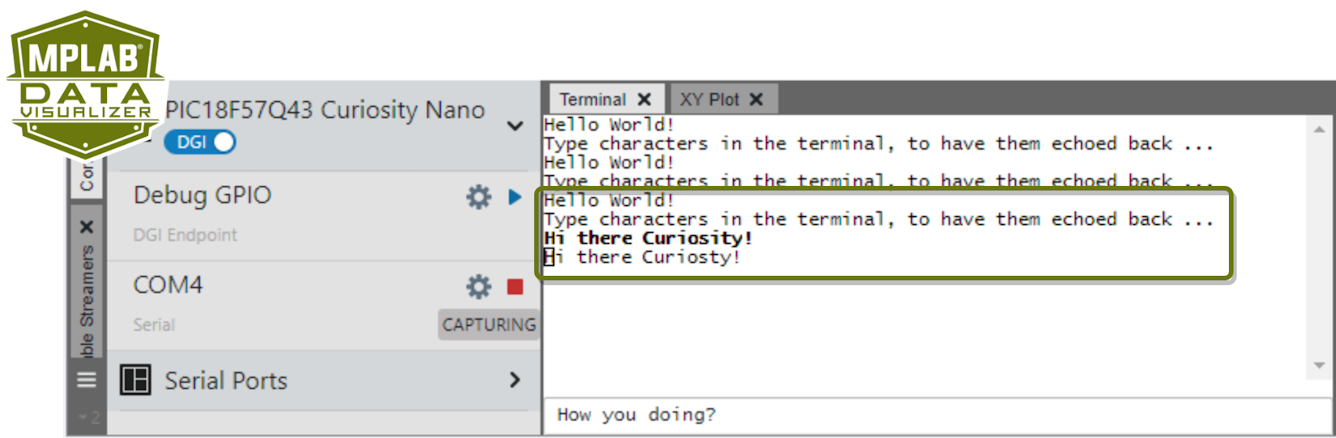
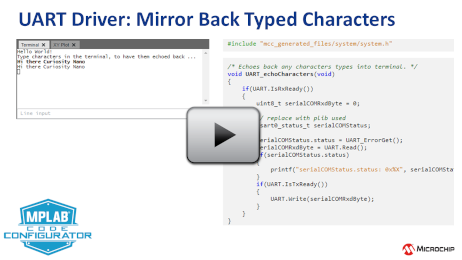
5.2.3.4 Running the UART Mirror Back Typed Characters
This example demonstrates how to send and receive data byte using UART read and write functions. A catch for a read error (if any) in the received byte is also implemented.
The following video shows a similar example from the MCC Melody API Reference for: PIC16F/18F, AVR.
5.2.4 Timer Example (Driver) - dsPIC
5.2.4.1 Running the Timer Toggle LED Example
Running the Timer Toggle LED example shows the LED on the board flash at a 100 ms period interval.
-
Example 100 ms:
5.2.4.2 Running the Timer Switch Frequency Example
An initial run of the Timer Switch Frequency example shows the LED on the board flash at a 500 ms period interval. Pressing the assigned button will swap the period between 500 ms and 100 ms.
-
Example 500 ms:
-
Example 100 ms:
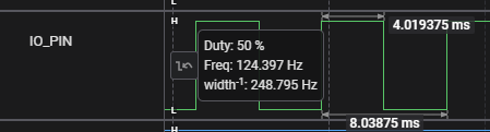
5.2.4.3 Running the Timer 125 Hz Output Signal Example
When running the Timer 125 Hz Output Signal Example, an 125 Hz output can be measured on the selected pin.
-
Output:
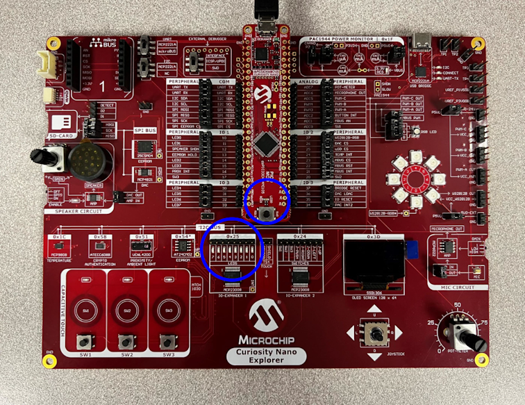
5.2.4.4 Example Board for the Timer Examples
The Timer example can be run on Curiosity Nano boards, such as the dsPIC33CK64MC105. In the image below, the circled LED on the Curiosity Nano is toggled according to the set timer period. An LED on the Curiosity Nano Explorer will flash alongside as it is wired up to the dsPIC LED.
All three Timer examples were tested using the hardware setup presented below.
5.2.5 Timer Example (PLIB) - PIC16F/18F
5.2.5.1 Running the Timer Toggle LED Example
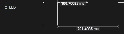
The image shows running the Timer Toggle LED, verifying the 100ms period using Debug GPIO on the MPLAB Data Visualizer. An example Curiosity Nano is used, but the example can be configured to run on any board.
-
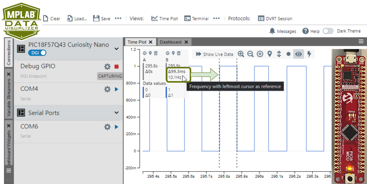 Tip: Two vertical cursors are added to verify the timer frequency. See configuration instructions below.Tip: A logic analyser can be used instead of Debug GPIO on the MPLAB Data Visualizer.
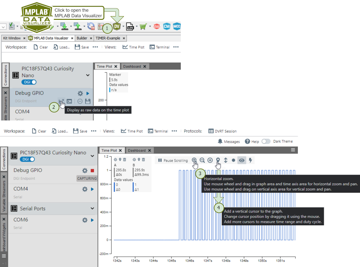
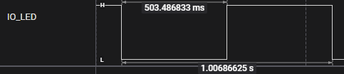
5.2.5.2 Running the Timer Switch Frequency Example
What will you see when running the Timer Switch Frequency example?
An initial run of the Timer Switch Frequency example shows the LED on the board flash at a 500 ms period interval. Pressing the assigned button will swap the period between 500 ms and 100 ms.
-
Example 500 ms:
-
Example 100 ms:
5.2.5.3 Running the Timer 125 Hz Output Signal Example
What will you see when running the Timer 125 Hz Output Signal example?
When running the Timer 125 Hz Output Signal Example, an 125 Hz output can be measured on the selected pin.
-
Output:
5.2.6 PWM Example - dsPIC
5.2.6.1 Running the PWM Duty Cycle Update with Timer Callback Example
Running the PWM duty cycle update with the timer callback example shows the LED brightness levels updated every 1 second. This cycle is then repeated in a loop with the LED changing from ‘ON Completely’, ‘Multiple levels of Brightness’ and ‘OFF’.
5.2.6.2 Running the PWM Duty Cycle Update with Button Press Example
Running the PWM duty cycle update with button press example shows the LED brightness levels updated every time the configured button is pressed. This cycle is then repeated in a loop with the LED changing from ‘ON Completely’, ‘Multiple levels of Brightness’ and ‘OFF’.
A single button is required for this example. Here are the available options for the dsPIC33CK64MC105 on the Curiosity Nano Explorer:
5.2.6.3 Running the PWM Duty Cycle Update with Analog Input Source Example
Running the PWM duty cycle update with analog input source example shows the LED brightness levels being updated corresponding to analog input. An ADC channel is used to receive input (from a potentiometer, for example), while the PWM updates the LED duty cycle accordingly.
5.2.6.4 Example Board for the PWM Examples
The PWM example can be run on Curiosity Nano boards, such as the dsPIC33CK64MC105. A single LED is required for these examples. The image below shows the hardware setup and available LED options for the dsPIC33CK64MC105 on the Curiosity Nano Explorer.
5.2.7 MCC Melody Notifications
This section details the hints, warnings and errors from MPLAB® Code Configurator (MCC) Melody.
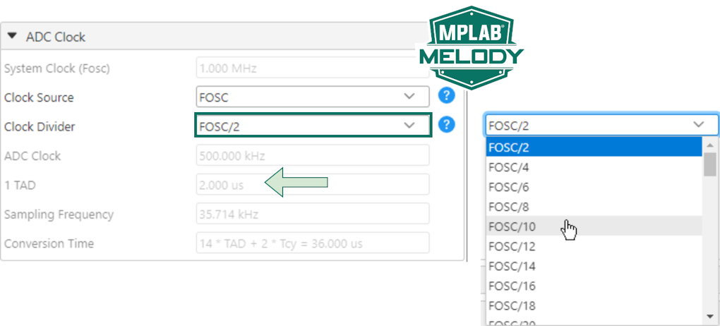
5.2.7.1 MCC Melody Hint: Slow Down ADC
Lower the ADC sampling frequency to be less the time it takes for an ADC Conversion (Tad).

How to fix it: ADCC Clock>Clock Divider>Slow down ADC Clock.
5.2.8 Adding Optional MCC Content within a Project
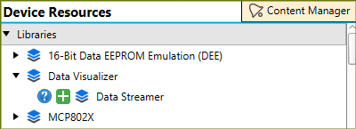
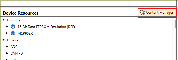
This section shows how to install MCC content that does not appear within the Device Resources panel.
-
Open a project in MCC Melody, select the Content Manager button in the Device Resources panel:
-
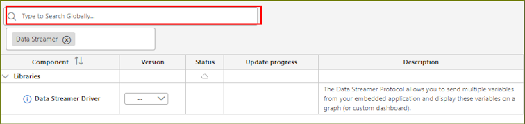
With Content Manager opened, search for the missing content. Here is an example after searching for the Data Streamer:
-
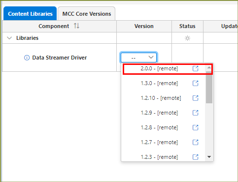
Now select the Latest/Required version of the content:
-
After selecting the latest version of the missing content, click the Apply button near the top of the Content Manager window and follow the prompts to fix any errors to apply the version.
-
MCC will refresh and the content will be displayed in the Device Resources panel: