This application demonstrates the ability of the MPLAB Harmony USB Device Stack to
support Vendor Device class.
Description
This application creates a USB CDC Device that enumerates as a custom vendor USB
device on the USB host PC. The device uses USB Device Layer Endpoint functions and
demonstrates the PC host's ability to control the LEDs on the board and query the
status of a switch through PC utility.
Downloading and building the
application
To clone or download this application from Github, go to the main page of this repository and then click Clone
button to clone this repository or download as zip file. This content can also be
downloaded using content manager by following these instructions.
Following table gives the details of project configurations, target device
used, hardware and its IDE. Open the project using the respective IDE and build
it.
Project Name
IDE
Target Device
Hardware / Configuration
pic32mz_ef_curiosity_2_0.X
MPLABX
PIC32MZ2048EFM144
Curiosity PIC32MZ EF 2.0 Development Board
pic32mx470_curiosity.X
MPLABX
PIC32MX470F512H
PIC32MX Curiosity Development Board
pic32mz_ef_sk.X
MPLABX
PIC32MZ2048EFH144
PIC32MZ Embedded Connectivity with FPU (EF) Starter Kit
pic32mz_ef_sk_freertos.X
MPLABX
PIC32MZ2048EFH144
PIC32MZ Embedded Connectivity with FPU (EF) Starter Kit
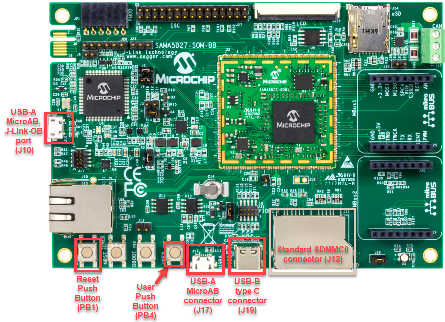
Powered the board with
an external power supply (or use the micro AB connector).
Setup the SD card
(Note: exFAT formatted SD Cards are not supported)
Download
harmony MPU bootstrap loader from this location.
Copy the
downloaded boot loader binary (boot.bin) and generated application
binary (harmony.bin) into the SD card.
Insert the SD
card into the SDMMC connector (SDMMC0) on the board.
Reset the board
by pressing the Push Button RESET, then START.
Connect USB to serial
cable to DBGU0 (to enable debug com port).
Connect the USB
Micro-AB Connector on the board to the computer using a micro USB cable.
LED near VDDCORE
inscription on the board indicates USB Device Configuration Set Complete event
(The USB device functionality has been activated by the USB Host).
Press the switch USER
to trigger communication from the USB Device to the USB Host.
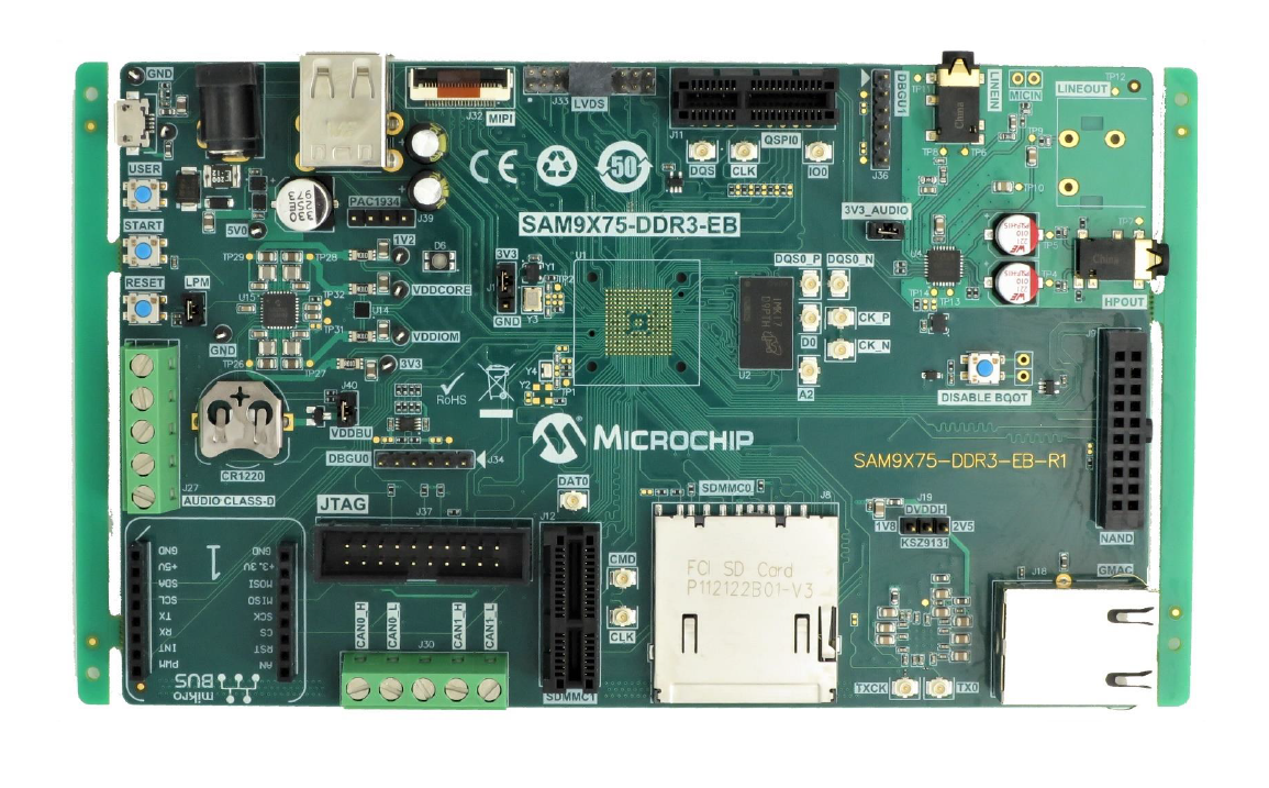
Setup the SD card
(Note: exFAT formatted SD Cards are not supported)
Download
harmony MPU bootstrap loader from this location.
Copy the
downloaded boot loader binary (boot.bin) and generated application
binary (harmony.bin) into the SD card.
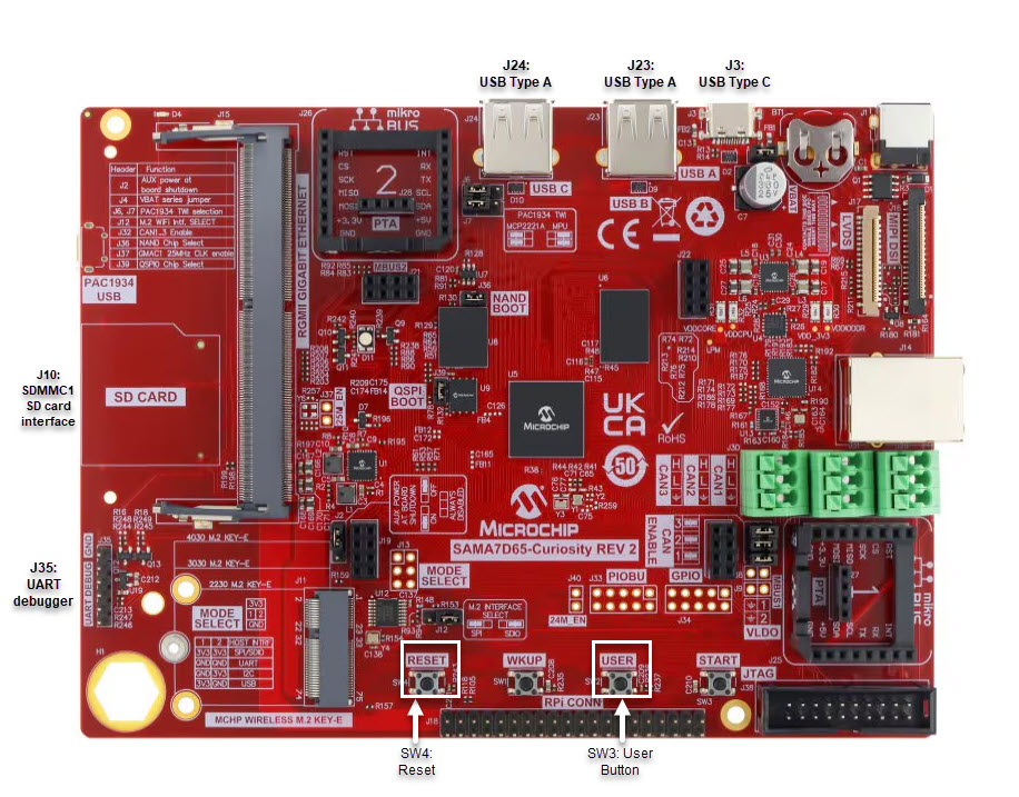
Insert the SD
card into the μSD-CARD connector (J6) on the board.(This connector is
present on the bottom face of the board)
Reset the board
by pressing the Push Button RESET.
Press the "START"
button to activate board start-up.
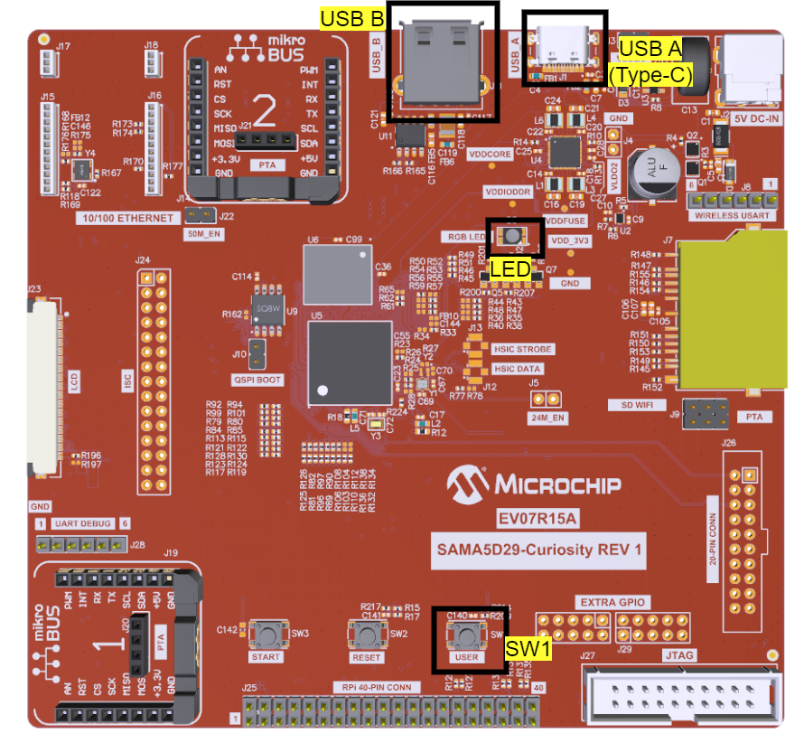
Connect the USB Type-C
(USB-A) Connector (J1) on the board to the computer using a USB Type-C
cable.
RGB LED (D5) turning to
Green indicates USB Device Configuration Set Complete event (The USB device
functionality has been activated by the USB Host).
Press the “USER” Push
Button (SW1) to trigger communication from the USB Device to the USB Host.
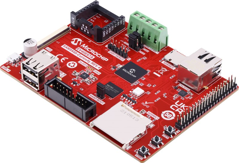
SAM9X75-Curiosity Development Board
Setup the SD card
(Note: exFAT formatted SD Cards are not supported)
Download
harmony MPU bootstrap loader from this location.
Copy the
downloaded boot loader binary (boot.bin) and generated application
binary (harmony.bin) into the SD card.
Insert the SD
card into the μSD-CARD connector (J14) on the board.
Reset the board
by pressing the Push Button RESET.
Press the "START"
button to activate board start-up.
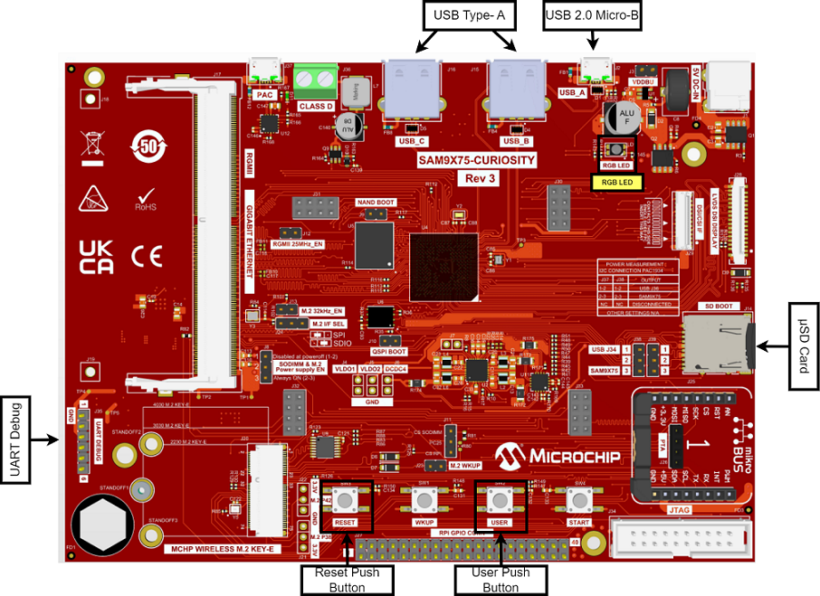
Connect the USB Micro-B
(USB_A) Connector (J2) on the board to the computer using a USB cable.
RGB LED (LD1) turning
to Green indicates USB Device Configuration Set Complete event (The USB device
functionality has been activated by the USB Host).
Press the “USER” Push
Button (SW2) to trigger communication from the USB Device to the USB Host.
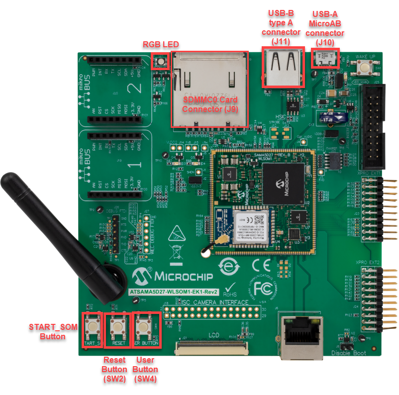
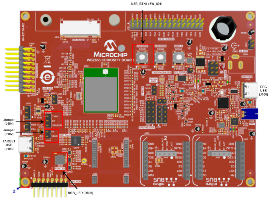
Use the USB micro-B
"USB DEVICE" connector (J200) to connect the USB Device to the USB Host PC.
LED1 indicates USB
Device Configuration Set Complete event (the USB device functionality has been
activated by the USB Host).
Press the switch SW0 to
trigger communication from the USB Device to the USB Host.
Running the Application
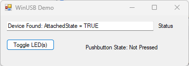
The Vendor device can be exercised by using the WinUSB PnP Demonstration
application, which is provided in the installation of MPLAB Harmony.
The LEDs on the demonstration board will indicate the USB state of the
device. This application allows the state of the LEDs on the board to be toggled and
indicates the state of a switch (pressed/released) on the board. Refer to the
Configuring the Hardware section for the selected target hardware.
To launch the application, open the executable WinUSB_PnP_Demo.exe
from the folder path
usb_apps_device/apps/vendor/bin/WinUSB_PnP_Demo.exe. A dialog box
similar to the following should appear:
The appropriate device family that is under testing should be selected in the
utility. Pressing the Toggle LED button will cause the LED on the board to toggle.
The Push button State field in the application indicates the state of a button on
connected USB Device. Pressing the switch on the development board will update the
Pressed/Not Pressed status of the Push button State field.
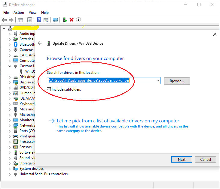
Note: The device family under test should be selected
appropriately. An incorrect selection will result in an invalid push button
status. Windows Operating system may select a wrong driver by default. If the
application does not run as expected it is suggested to look into the Windows
Device Manager and see if the Microchip WinUSB Device is not shown with a Yellow
mark. If so, the drivers should be selected manually from the application
path.
Manual selection of
Drivers
To specifically select the driver, open the device manager and look
for device named as WinUSB Device with a Yellow mark. Right click and select
Update Driver Software. Select Browse my computer for drivers.
Select the drivers in application path
..\usb_apps_device\apps\vendor\driver.

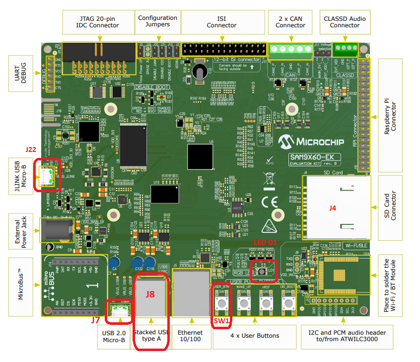 Note: Reset push button on SAM9X60 EK is labelled as SW3.