
4.1 Using Output Ripple (Type 1)
In a buck converter, the output ripple primarily arises from two main factors: the output capacitance and its Equivalent Series Resistance (ESR). The output capacitance serves to store and release energy during the switching cycle, helping to smooth variations in the output voltage.
However, due to the finite charging and discharging times of the output capacitor, small fluctuations in output voltage occur, resulting in ripple. Typically, this ripple amplitude (depicted as ΔVo_Cout in Figure 4-1) is minimal and is out of phase with inductor current, making it unsuitable for feedback control purposes. ΔVo_Cout can be calculated using Figure 1.
Where:
FSW = Switching Frequency
Cout = Output Capacitance
ΔIL = Inductor Ripple Current
However, the ESR of the output capacitor introduces further voltage fluctuations (depicted as ΔVo_ESR in Figure 4-1) due to the inductor current ripple. If the ESR is high enough, it can naturally provide a significant amount of ripple at the output which is also in phase with inductor current.
Note that the parasitic inductance ripple in discussion was ignored, assuming that the layout is good and capacitor Equivalent Series Inductance (ESL) is not abnormally high. For ease of reference, we have assigned type numbers to different control loop designs. This method, where the output ripple is used for the feedback ripple, is designated as type 1.
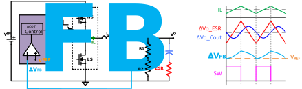
Multi-layer ceramic capacitors (MLCC), aluminum electrolytic, tantalum, and polymer capacitors are commonly used in DC/DC switching regulator circuits. A quick comparison can be seen in Table 4-1. Electrolytic capacitors, in particular, have higher ESR values, contributing to a larger output ripple. Thus, if an application can tolerate a substantial amount of ripple at the output, simply using a high ESR capacitor may suffice for stable operation of a COT or ACOT converter.
| Technology | ESR | ESL | Voltage Stability | Temperature Stability | Capacitance/Unit Volume |
|---|---|---|---|---|---|
| Aluminum Electrolytic | Highest | Highest | Good | Lowest | High |
| Tantalum | Medium | Medium | Best | Good | High |
| Solid Polymer | Low | Low | Best | Good | High |
| Multilayer Ceramic | Lowest | Lowest | Poor | Good | Medium |
Figure 3 explains how to calculate the required ESR for a given inductor ripple current (ΔIL), reference voltage (VREF), output voltage (VO), and feedback ripple voltage (ΔVFB).