
4.1.1 Abnormal Switching Behavior and Critical ESR
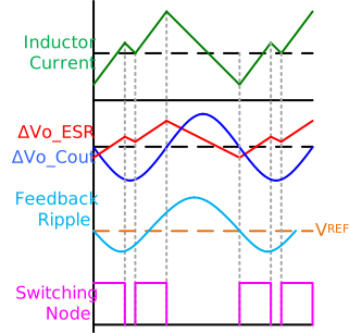
Figure 4-2 and Figure 4-3 depict the steady-state waveforms of inductor current (IL), capacitive ripple voltage (ΔVo_Cout), ESR ripple (Vo_ESR), feedback ripple voltage, and the switching node. These figures illustrate cases with larger and smaller ESR values, respectively. In Figure 4-2, the ESR ripple dominates the capacitive ripple and the converter operates normally.
However, when the ESR ripple is insufficient to dominate the capacitive ripple, as shown in Figure 4-3, erratic switching behavior occurs. In this scenario, the high side FET is immediately turned back on after minimum OFF time, resulting in double pulsing and significant fluctuations in inductor current and output voltage.
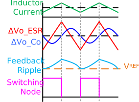
As shown in Figure 4-2, during the HS FET ON time if the positive slope of ΔVo_ESR is greater than or equal to the negative slope of ΔVo_Cout, the output voltage (VO) will consistently remain higher than the reference voltage (VREF). This condition ensures normal operation.
Conversely, Figure 4-3 shows the situation where the ESR ripple slope is less than the capacitive ripple slope during the HS FET ON time, resulting in abnormal switching. We could call the ESR value when both slopes match as the critical ESR, because below the critical ESR value, the abnormal switching begins. To derive the equation for the critical ESR value, we can follow the steps outlined below.
When the high side FET is ON, the slope of Vo_ESR can be expressed as shown in Figure 3.
The slope of ΔVo_Cout can be calculated as shown in Figure 4.
Combine Figure 3 and Figure 4 to get the critical value of ESR:
In other words, the stability criteria when the ESR ripple is sufficient for the feedback ripple (Type 1) can be expressed as:
One crucial takeaway from this discussion is that, if the feedback ripple deviates from being in phase with the inductor current or falls outside of the recommended amplitude range, it can lead to abnormal switching behavior, laying the groundwork for potential failure. This is true regardless of the source of feedback ripple.
The Type 1 method is the simplest control loop scheme for ACOT, as it does not require any additional components beyond the parasitic components. However, it has the drawback of needing a substantial amount of output ripple, which also needs to be in phase with the inductor current, requiring a large output capacitor ESR. Since a large output ripple is undesirable in many applications, the following sections present other control loop types that reduce dependence on the output ripple.