
4.2 Using a Feed-Forward Capacitor (Type 2)
Large output voltage ripple is undesirable for most applications, as modern systems demand a clean output from the power supply. A common approach to reducing ripple is to select a low ESR output capacitor.
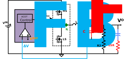
However, when the output ripple amplitude decreases due to low ESR, relying solely on the ESR ripple method can become problematic. In such cases, where medium output ripple is present (more than 20 – 40 mV or the minimum limit specified in the device data sheet), introducing a feed-forward capacitor (CFF) can be beneficial. The CFF is placed in parallel with the top feedback resistor (as illustrated in Figure 4-4) and can effectively enhance the feedback output ripple.
As illustrated in Figure 4-5 (AC gain without CFF) and Figure 4-6 (AC gain and phase boost with CFF), the feed-forward capacitor directs high-frequency ripple to the FB pin, ensuring a phase boost around the middle of the relevant bandwidth. This method effectively manages feedback ripple if enough output ripple is present.
|
|
|
CFF introduces a gain boost after its zero frequency (FZ) and a phase boost is at a maximum between the zero and pole frequencies (FP). FP and FZ can be calculated using Figure 4 and Figure 5. Increasing the value of CFF shifts the zero and pole to lower frequencies, and decreasing the value CFF shifts the zero and pole to higher frequencies. The gain at DC is set by R1 and R2.
A typical choice for CFF is between 1 nF to 100 nF (10 nF is a good starting point), if R1 and R2 are in the kΩ range.
The impedance of CFF at the switching frequency should be much lower than R1 and R2, hence the minimum value of CFF can be calculated using Equation 4-9(considering the impedance of CFF to be at least an order of magnitude lower than the impedance of R1 in parallel with R2).