
3.6.3.1.2 Example of Clock Configuration on PIC32CM LS00 Curiosity Nano+ Touch Evaluation Kit
Description:
This application demonstrates how the clock system generates and distributes the clock for the processor and peripherals.
This example application shows how to use the clock configuration to set up the device to run at the maximum possible speed. A prescaled clock signal is routed to GCLK pin to measure the frequency and accuracy of the internal device clock.
Modules/Technology Used
- Peripheral Modules
- EVSYS
- NVMCTRL
- PM
- PORT
- SYSTICK
The MCC Harmony project graph with all the components would look like this: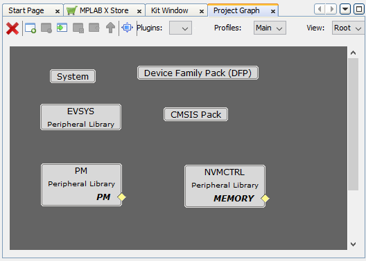
Hardware Used
Software/Tools Used
This project has been verified to work with the following versions of software tools:
Refer Project Manifest present in harmony-manifest-success.yml under the project folder firmware\clock_config\src\config\pic32cm_ls00_cnano
- Refer the Release Notes to know the MPLAB X IDE and MCC Plugin version.
- Saleae Logic Software.
Because Microchip regularly updates tools, occasionally issue(s) could be discovered while using the newer versions of the tools. If the project does not seem to work and version incompatibility is suspected. It is recommended to double-check and use the same versions that the project was tested with. To download original version of MPLAB Harmony v3 packages, refer to document How to Use the MPLAB Harmony v3 Project Manifest Feature (DS90003305).
Setup
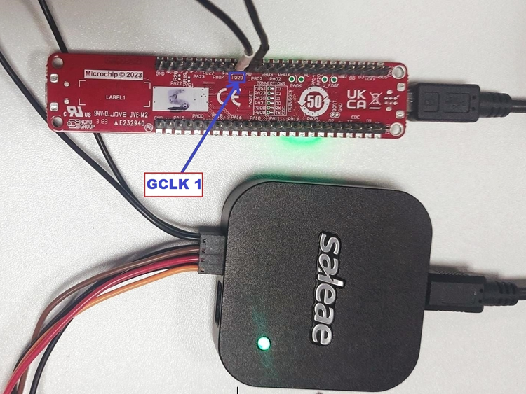
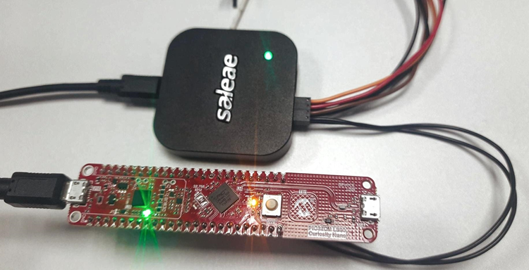
- Connect the PIC32CM LS00 Curiosity Nano+ Touch Evaluation Kit to the Host PC as a USB Device through a Type-A male to micro-B USB cable connected to Micro-B USB (Debug USB) port.
- To establish the connection with the Saleae Logic Analyzer to the Host PC.
- Configure the Channel 0 is PB23 to
monitor the GCLK.
Programming hex file
The pre-built hex file can be programmed by following the below steps.
- Open MPLAB X IDE
- Close all existing projects in IDE, if any project is opened.
- Go to File -> Import -> Hex/ELF File
- In the Import Image File
window,
- Create Prebuilt Project,
- Click the Browse button to select the prebuilt hex file.
- Select Device as PIC32CM5164LS00048.
- Ensure the proper tool is selected under Hardware Tool and click on Next button.
- Select Project Name and Folder,
- Select appropriate project name and folder and click on Finish button
- Create Prebuilt Project,
- In MPLAB X IDE, click on Make and Program Device button to program the device.
- Follow the steps in Running the Demo section below.
Programming/Debugging Application Project
- Open the project (clock_config\firmware\clock_config\pic32cm_ls00_cnanogroup) in MPLAB X IDE.
- Ensure PIC32CM LS00 Curiosity Nano is selected as hardware tool to program/debug the application.
- Build the code and program the device by clicking on the Make and Program button in MPLAB X IDE tool bar.
- Follow the steps in Running the Demo section below.
Running the Demo
- Open the Saleae logic application on the PC (from the Windows® Start menu by pressing the Start button).
- An LED1 on the PIC32CM LS00 Curiosity
Nano+ Touch Evaluation Kit is toggles continuously using the SysTick Timer.
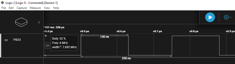
- Observe a clock of 4 MHz on the clock output pin PB23.
Logic Analyzer Output
- The following clock output is displayed
on the Logic Analyzer.
Comments
- Reference Training Module: Arm TrustZone Getting Started Application on PIC32CM LS60 (Arm Cortex-M23) MCUs.
- This application demo builds and
works out of box by following the instructions above in Running the Demo
section. If the user needs to enhance/customize this application demo, should use the
MPLAB Harmony v3 Software framework. Refer links below to setup and build the
applications using MPLAB Harmony.
- How to Setup MPLAB Harmony v3 Software Development Framework (DS90003232).
- How to Build an Application by Adding a New PLIB, Driver, or Middleware to an Existing MPLAB Harmony v3 Project (DS90003253).
- How to Set up the Tools Required to Get Started with MPLAB® Harmony v3 and MCC
- Create a new MPLAB Harmony v3 project using MCC
- Update and Configure an Existing MHC-based MPLAB Harmony v3 Project to MCC-based Project